M61323FP 데이터 시트보기 (PDF) - Renesas Electronics
부품명
상세내역
제조사
M61323FP Datasheet PDF : 20 Pages
| |||
M61323SP/FP
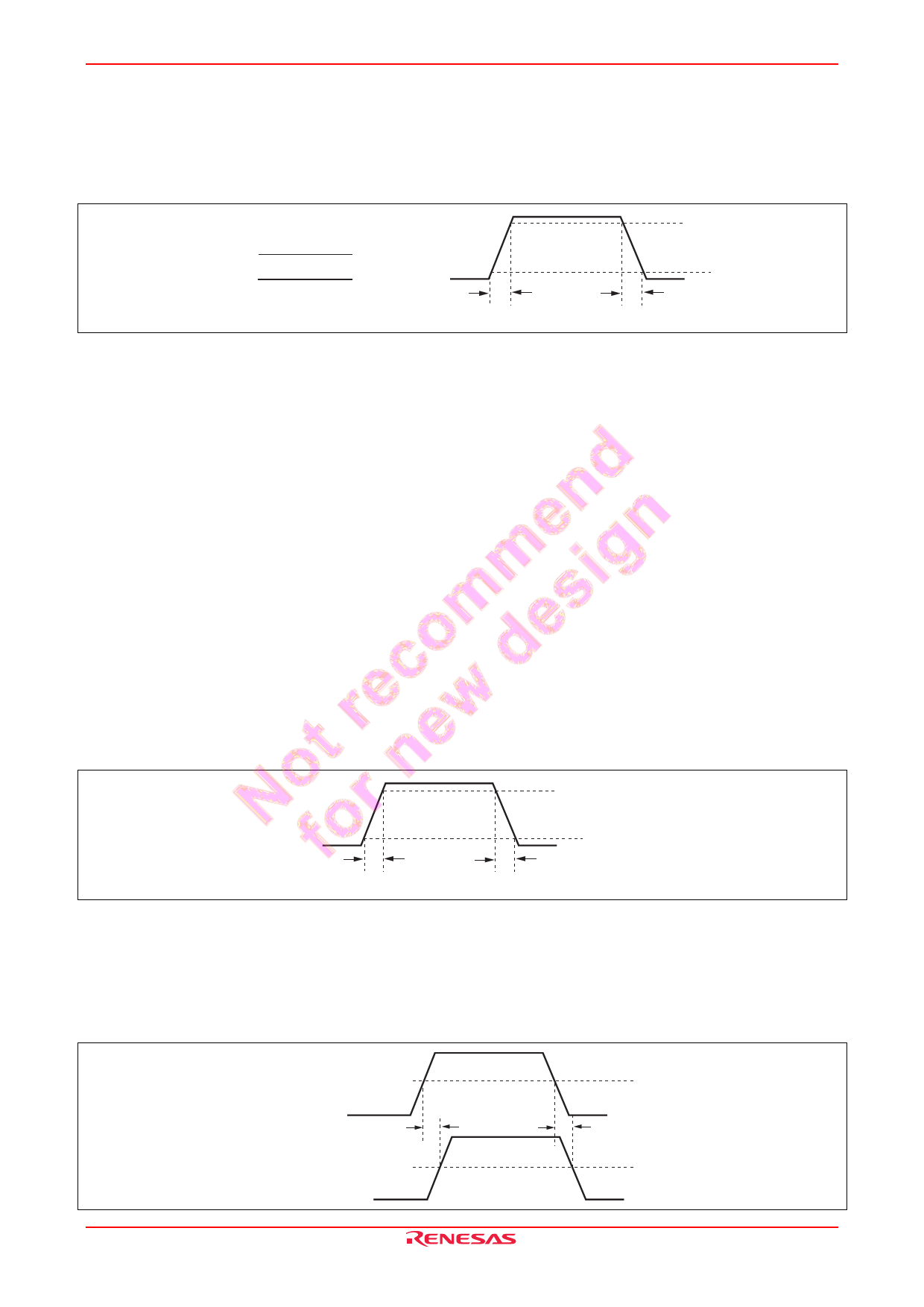
Pulse Characteristic 1, 2
1. The conditions is as table (SG5 amplitude 0.7 VP-P). Set SW13 to GND (or OPEN).
2. Measure rising Tri and falling Tfi for 10% to 90% of the input pulse with active probe.
3. Next, measure rising Tro and falling Tfo for 10% to 90% of the output pulse with active probe.
4. Pulse characteristic Tr1, Tf1 (Tr2, Tf2) is
100%
90%
Tr1 (Tr2) = √ (Tro)2 − (Tri)2 (ns)
0%
Tf1 (Tf2) = √ (Tfo)2 − (Tfi)2 (ns)
Tr
10%
Tf
<HV-SW>
High Level Output Voltage 1, 2/Low Level Output Voltage 1, 2
1. The conditions is as table. Input SG8 to pin 7 (or pin 8). Set SW13 to GND, read the output high level and low
voltage of TP19, TP18. The value is as Vdch1, Vdcl1.
2. Input SG8 to pin 15 (or pin 16). Set SW13 to OPEN, read the output high level and low voltage of TP19, TP18.
The value is as Vdch2, Vdcl2.
Input Threshold Voltage H/Input Threshold Voltage L
1. Set SW13 to GND (or OPEN). Gradually increasing the voltage of pin 7 (or pin 15) from 0 V, measure the input
voltage of pin 7 (or pin 15) when the TP19 voltage turned high level (3.8 V or more). The value is as VithH.
2. Gradually decreasing the voltage of pin 7 (or pin 15) from 3 V, measure the input voltage of pin 7 (or pin 15) when
the TP19 voltage turned low level (0.5 V or less). The value is as VithL.
3. In the same way, measure the input voltage of pin 8 (or pin 16) as VithH, VithL.
Rising Time/Falling Time
1. The conditions is as table. This measurement shall use active probe.
2. Measure rising Tri and falling Tfi for 20% to 80% of the output pulse as Tr3, Tf3 (Tr4, Tf4).
100%
80%
0%
Tr'
20%
Tf'
Rising Delay Time/Falling Delay Time
Set SW13 to GND (or OPEN), input SG8 to pin 7 (or pin 15).
Measure the rising delay time HVDr and the falling delay time HVDf.
In the same way, measure HVDr and HVDf when input SG8 to pin 8 (or pin 16)
SG8
HVDr
Waveform output
50%
HVDf
50%
REJ03F0201-0201 Rev.2.01 Mar 31, 2008
Page 9 of 19
Share Link: 