MAX6304ESA 데이터 시트보기 (PDF) - Maxim Integrated
부품명
상세내역
제조사
MAX6304ESA Datasheet PDF : 12 Pages
| |||
+5V, Low-Power µP Supervisory Circuits
with Adjustable Reset/Watchdog
ELECTRICAL CHARACTERISTICS (continued)
(VCC = +2V to +5.5V, TA = TMIN to TMAX, unless otherwise noted. Typical values are at VCC = +5V and TA = +25°C.)
PARAMETER
SYMBOL
CONDITIONS
MIN TYP MAX UNITS
WATCHDOG TIMER
WDI, WDS Input Threshold
WDI Pulse Width
WDI, WDS Leakage Current
VIH
VIL
tWP
VCC = 4.5V to 5.5V
VCC = 2V to 4.5V
Extended mode disabled
0.7 x VCC
30
60
V
0.3 x VCC
ns
±1
µA
WDI Sink/Source Current (Note 4)
Extended mode enabled
±70
µA
Watchdog Timeout Period
(Note 3)
tWD
WDS = GND, CSWT = 1500pF
WDS = VCC, CSWT = 1500pF
2.8
4.0
5.2
ms
1.4
2.0
2.6
s
Note 1: Reset is guaranteed valid from the selected reset threshold voltage down to the minimum VCC.
Note 2: WDS = VCC, WDI unconnected.
Note 3: Precision timing currents of 500nA are present at both the SRT and SWT pins. Timing capacitors connected to these nodes
must have low leakage consistent with these currents to prevent timing errors.
Note 4: The sink/source is supplied through a resistor, and is proportional to VCC (Figure 8). At VCC = 2V, it is typically ±24µA.
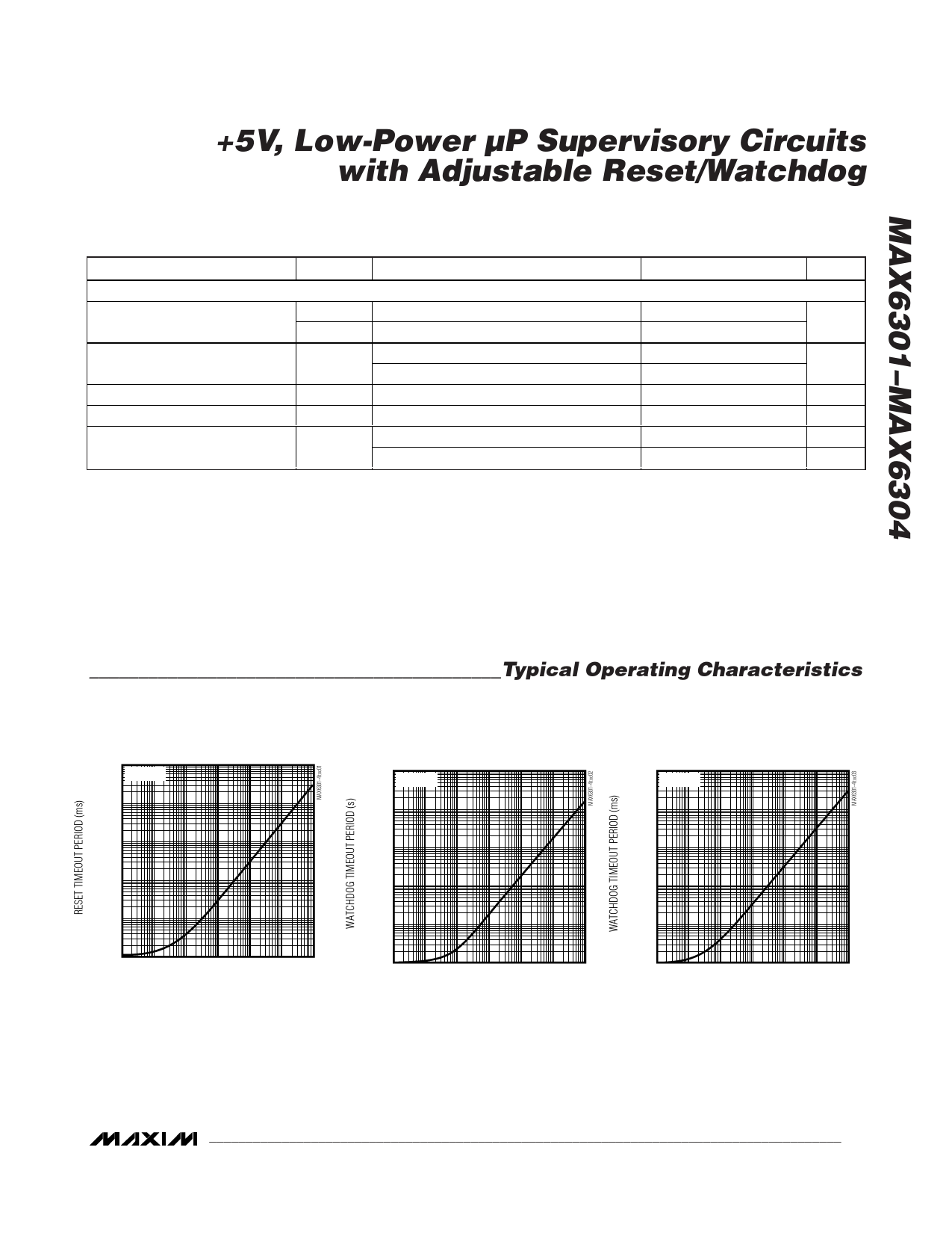
__________________________________________Typical Operating Characteristics
(CSWT = CSRT = 1500pF, TA = +25°C, unless otherwise noted.)
10,000
RESET TIMEOUT PERIOD
vs. CSRT
VCC = 5V
1000
10,000
EXTENDED-MODE
WATCHDOG TIMEOUT PERIOD vs. CSWT
(WDS = VCC)
VCC = 5V
1000
10,000
NORMAL-MODE
WATCHDOG TIMEOUT PERIOD vs. CSWT
(WDS = GND)
VCC = 5V
1000
100
100
100
10
10
10
1
1
1
0
0.001 0.01
0.1 1 10
CSRT (nF)
100 1000
0
0.001 0.01
0.1 1 10
CSWT (nF)
100 1000
0.1
0.001 0.01
0.1 1 10
CSWT (nF)
100 1000
_______________________________________________________________________________________ 3
Share Link: 