MAX6647 데이터 시트보기 (PDF) - Maxim Integrated
부품명
상세내역
제조사
MAX6647
Maxim Integrated

MAX6647 Datasheet PDF : 16 Pages
| |||
+145°C Precision SMBus-Compatible Remote/
Local Sensors with Overtemperature Alarms
A
B
C
D
EF
G
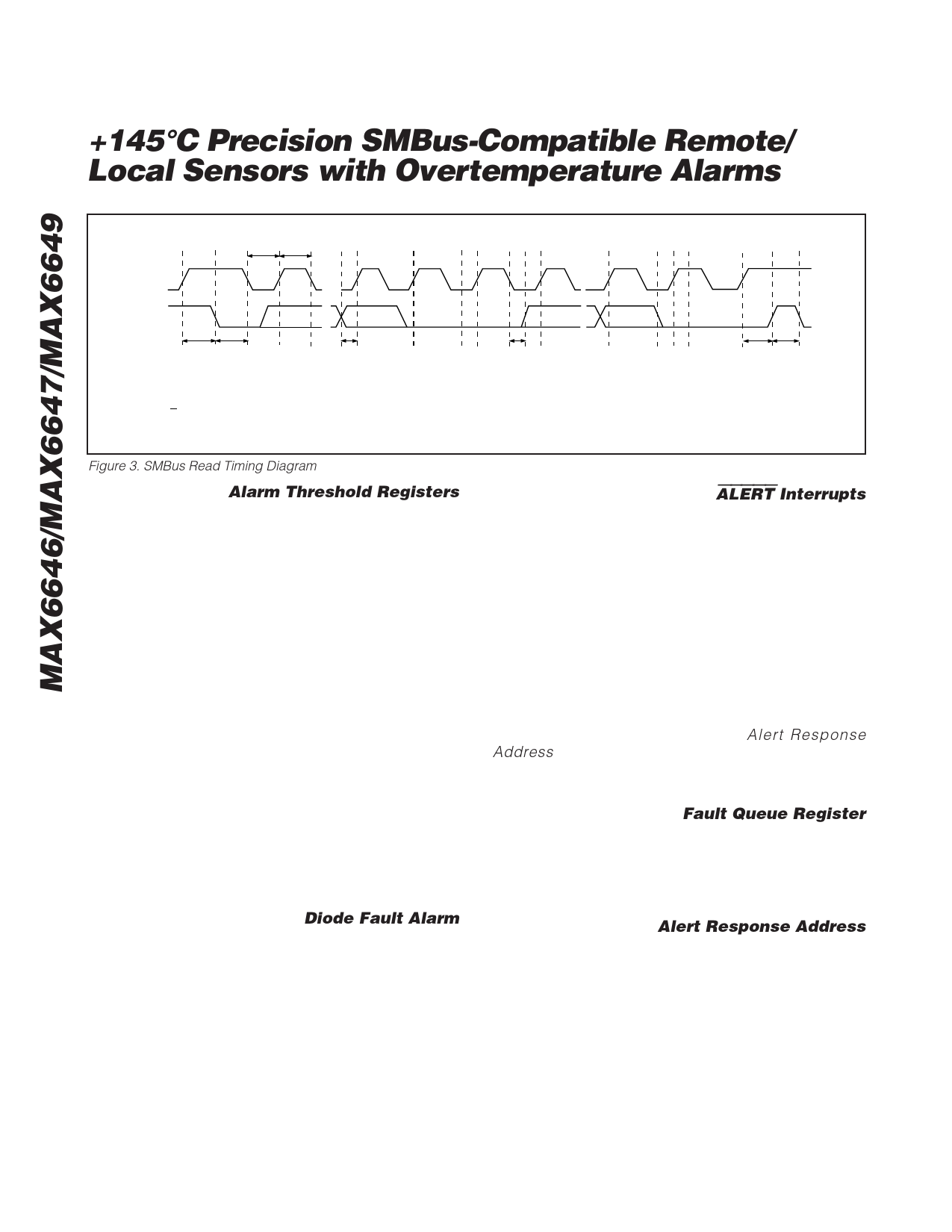
tLOW tHIGH
SMBCLK
H
I JK
LM
SMBDATA
tSU:STA tHD:STA
A = START CONDITION
B = MSB OF ADDRESS CLOCKED INTO SLAVE
C = LSB OF ADDRESS CLOCKED INTO SLAVE
D = R/W BIT CLOCKED INTO SLAVE
E = SLAVE PULLS SMBDATA LINE LOW
tSU:DAT
tHD:DAT
F = ACKNOWLEDGE BIT CLOCKED INTO MASTER
G = MSB OF DATA CLOCKED INTO MASTER
H = LSB OF DATA CLOCKED INTO MASTER
I = MASTER PULLS DATA LINE LOW
tSU:STO tBUF
J = ACKNOWLEDGE CLOCKED INTO SLAVE
K = ACKNOWLEDGE CLOCK PULSE
L = STOP CONDITION
M = NEW START CONDITION
Figure 3. SMBus Read Timing Diagram
Alarm Threshold Registers
Four registers store ALERT threshold values—one high-
temperature (THIGH) and one low-temperature (TLOW)
register each for the local and remote channels. If either
measured temperature equals or exceeds the corre-
sponding ALERT threshold value, the ALERT interrupt
asserts.
The MAX6646/MAX6647 local (internal) ALERT THIGH
register POR state is 0101 0101, or +85°C, while the
remote (external) ALERT THIGH register POR state is
0101 1111, or +95°C.The MAX6649 POR state of both
ALERT THIGH registers is 0101 0101, or +85°C. The POR
state of the local and remote TLOW registers for all
devices is 0000 0000, or 0°C.
Two additional registers store remote and local alarm
threshold data corresponding to the OVERT output. The
values stored in these registers are high-temperature
thresholds. If either of the measured temperatures equals
or exceeds the corresponding alarm threshold value, an
OVERT output asserts. The MAX6646/MAX6647 local
(internal) OVERT register POR state is 0101 0101, or
+85°C, while the remote (external) OVERT register POR
state is 0111 1101, or +125°C. The MAX6649 POR state
of both OVERT registers is 0101 0101, or +85°C.
Diode Fault Alarm
A continuity fault detector at DXP detects an open cir-
cuit between DXP and DXN, or a DXP short to VCC,
GND, or DXN. If an open or short circuit exists, the
external temperature register is loaded with 1111 1111.
If the fault is an open-circuit fault bit 2 (OPEN), the sta-
tus byte is set to 1. In the MAX6649, ALERT is activated
at the end of the conversion. Immediately after POR,
the status register indicates that no fault is present. If a
fault is present upon power-up, the fault is not indicated
until the end of the first conversion.
ALERT Interrupts
The ALERT interrupt occurs when the internal or external
temperature reading exceeds a high- or low-temperature
limit (programmed) or in the MAX6649, when the remote
diode is disconnected (for continuity fault detection). The
ALERT interrupt output signal is latched and can be
cleared only by either reading the status register or by
successfully responding to an alert response address. In
both cases, the alert is cleared if the fault condition no
longer exists. Asserting ALERT does not halt automatic
conversion. The ALERT output is open drain, allowing
multiple devices to share a common interrupt line.
The MAX6646/MAX6647/MAX6649 respond to the
SMBus alert response address, an interrupt pointer
return-address feature (see the Alert Response
Address section). Prior to taking corrective action,
always check to ensure that an interrupt is valid by
reading the current temperature.
Fault Queue Register
In some systems, it may be desirable to ignore a single
temperature measurement that falls outside the ALERT
limits. Bits 1 and 2 of the fault queue register (address
22h) determine the number of consecutive temperature
faults necessary to set ALERT (see Tables 3 and 4).
Alert Response Address
The SMBus alert response interrupt pointer provides
quick fault identification for simple slave devices that
lack the complex, expensive logic needed to be a bus
master. Upon receiving an ALERT interrupt signal, the
host master can broadcast a receive byte transmission
to the alert response slave address (0001 100).
Following such a broadcast, any slave device that gen-
erated an interrupt attempts to identify itself by putting
its own address on the bus.
8
Share Link: