MAX6848 데이터 시트보기 (PDF) - Maxim Integrated
부품명
상세내역
제조사
MAX6848
Maxim Integrated

MAX6848 Datasheet PDF : 12 Pages
| |||
Low-Power, Adjustable Battery Monitors with
Hysteresis and Integrated µP Reset
Manual Reset
Many microprocessor-based products require manual
reset capability, allowing the operator, a test technician,
or external logic circuitry to initiate a reset while the
monitored supplies remain above their reset thresholds.
These devices have a dedicated active-low MR pin.
When MR is pulled low, RESET asserts a one-shot low
pulse for the MR reset timeout period. The MR input has
an internal 1.5kΩ pullup resistor to VCC and can be left
unconnected if not used. MR can be driven with CMOS-
logic levels, open-drain/open-collector outputs, or a
momentary pushbutton switch to GND (the MR function
is internally debounced for the tDEB timeout period) to
create a manual reset function. If MR is driven from long
cables, or if the device is used in a noisy environment,
connect a 0.1µF capacitor from MR to GND to provide
additional noise immunity (see Figure 4).
Hysteresis
Hysteresis increases the comparator’s noise margin by
increasing the upper threshold or decreasing the lower
threshold. The hysteresis prevents the output from
oscillating (chattering) when monitor input is near the
low-battery threshold. This is especially important for
applications where the load on the battery creates sig-
nificant fluctuations in battery voltages (see Figures 2
and 3).
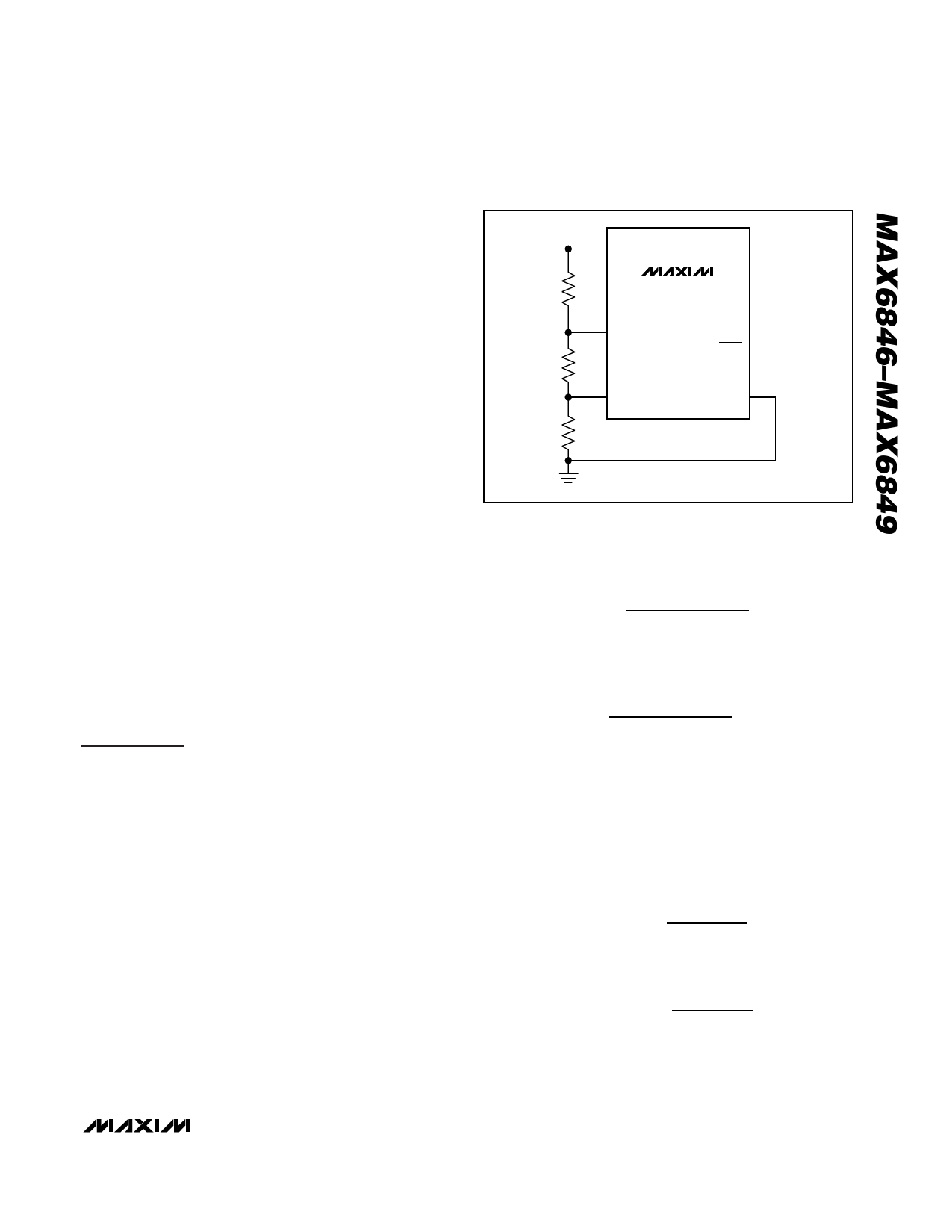
For the MAX6846/MAX6847, hysteresis is set using three
external resistors (see Figure 5). The MAX6848/MAX6849
have dual, low-battery input levels. Each input level has a
5% (typ) hysteresis.
Applications Information
Resistor-Value Selection (Programming
the Adjustable Thresholds)
MAX6846/MAX6847
VDD
VDD
LBO*
R1
MAX6846
MAX6847
MAX6848
LTHIN MAX6849
(LBOH)
R2
(LBOL)
HTHIN
GND
R3
* FOR THE MAX6846/MAX6847.
( ) FOR THE MAX6848/MAX6849.
Figure 5. Adjustable Threshold Selection
2) Calculate R3 based on RTOTAL and the desired
upper trip point:
R3 = 615mV × RTOTAL
VTRIPHIGH
3) Calculate R2 based on RTOTAL, R3, and the desired
lower trip point:
R2
=
615mV × RTOTAL
VTRIPLOW
-
R3
4) Calculate R1 based on RTOTAL, R3, and R2:
R1 = RTOTAL - R2 - R3
VLTH = VHTH = 615mV
VTRIPLOW
=
VLTH
×
R1 + R2 + R3
R2 + R3
VTRIPHIGH
=
VHTH
×
R1 + R2 + R3
R3
RTOTAL = R1 + R2 + R3
Use the following steps to determine values for R1, R2,
and R3 of Figure 5.
1) Choose a value for RTOTAL, the sum of R1, R2, and
R3. Because the MAX6846/MAX6847 have very high
input impedance, RTOTAL can be up to 500kΩ.
VLTH- = VHTH- = 582mV
LBOL low-trip level:
MAX6848/MAX6849
VTRIPLOW
=
VLTH-
×
R1 + R2 + R3
R2 + R3
LBOH low-trip level:
VTRIPHIGH
=
VHTH-
×
R1 + R2 + R3
R3
RTOTAL = R1 + R2 + R3
Use the following steps to determine values for R1, R2,
and R3 of Figure 5.
_______________________________________________________________________________________ 9
Share Link: