MAX6951EEE 데이터 시트보기 (PDF) - Maxim Integrated
부품명
상세내역
제조사
MAX6951EEE Datasheet PDF : 19 Pages
| |||
Serially Interfaced, +2.7V to +5.5V,
5- and 8-Digit LED Display Drivers
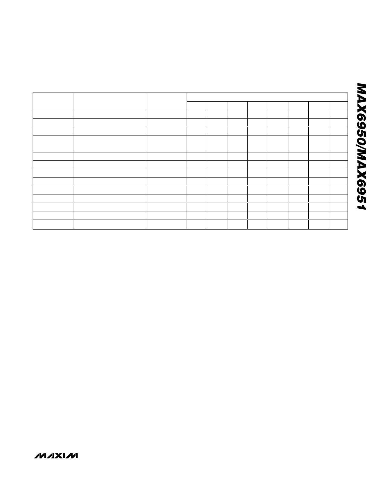
Table 4. Initial Power-Up Register Status
REGISTER
POWER-UP CONDITION
ADDRESS
CODE (HEX)
D7
D6
REGISTER DATA
D5
D4
D3
D2
D1
D0
Decode
No decode for digits 7–0
0x01
0
0
0
0
0
0
0
0
Intensity
1/16 (min on)
0x02
X
X
X
X
0
0
0
0
Scan Limit Display 5 digits: 0 1 2 3 4
0x03
X
X
X
X
X
1
0
0
Configuration Shutdown enabled/blink
speed is slow/blink disabled
0x04
X
X
X
0
0
0
0
0
Display Test Normal operation
0x07
X
X
X
X
X
X
X
0
Digit 0
Blank digit, both planes
0x60
0
0
0
0
0
0
0
0
Digit 1
Blank digit, both planes
0x61
0
0
0
0
0
0
0
0
Digit 2
Blank digit, both planes
0x62
0
0
0
0
0
0
0
0
Digit 3
Blank digit, both planes
0x63
0
0
0
0
0
0
0
0
Digit 4
Blank digit, both planes
0x64
0
0
0
0
0
0
0
0
Digit 5
Blank digit, both planes
0x65
0
0
0
0
0
0
0
0
Digit 6
Digit 7
Blank digit, both planes
Blank digit, both planes
0x66
0x67
0
0
0
0
0
0
0
0
0
0
0
0
0
0
0
0
Scan-Limit Register
The scan-limit register sets how many digits are dis-
played, from one to eight digits. It is possible to set the
MAX6950 (the five-digit part) to scan six, seven, or
eight digits. The MAX6951 set to eight digits displays
five digits less brightly than if it had been set to scan
five digits, but the brightness would match that of a
MAX6951 used in the same system if the Intensity reg-
isters are set to the same value. For example, consider
an 11-digit requirement. This can be served by using a
MAX6950 to drive five digits plus a MAX6951 to drive
six digits. Both parts are configured to drive six digits to
ensure the brightness is the same.
The digits are displayed in a multiplexed manner with a
typical display scan rate of 1kHz with five digits dis-
played or 625Hz with eight digits displayed with fOSC =
4MHz. Since the number of scanned digits affects the
display brightness, the Scan-Limit register should not
be used to blank portions of the display (such as for
leading-zero suppression). Table 12 lists the scan-limit
register format.
Intensity Register
Digital control of display brightness is provided by an
internal pulse-width modulator, which is controlled by the
lower nibble of the intensity register (Figure 4). The mod-
ulator scales the average segment current in 16 steps
from a minimum of 15/16 down to 1/16 of the peak cur-
rent. The minimum interdigit blanking time is set to 1/16
of a cycle. See Table 13 for Intensity register format.
Decode Mode Register
The decode mode register sets hexadecimal code
(0–9, A–F) or no-decode operation for each digit. Each
bit in the register corresponds to one digit. A logic high
selects hexadecimal code font decoding for that digit,
while logic low bypasses the decoder. Digits may be
set for decode or no-decode in any combination.
Examples of the decode mode control register format
are shown in Table 14.
When the hexadecimal code-decode mode is used, the
decoder looks only at the lower nibble of the data in the
digit register (D3–D0), disregarding bits D6–D4. D7,
which sets the decimal point (SEG DP), is independent
of the decoder, and is positive logic (D7 = 1 turns the
decimal point on). Table 15 lists the hexadecimal code
font. When no-decode is selected, data bits D7–D0 cor-
respond to the segment lines of the MAX6950/
MAX6951. Table 15 shows the one-to-one pairing of
each data bit to the appropriate segment line.
Display Digit Registers
The MAX6950/MAX6951 use a digit register to store the
data that the user wishes to display on the LED digits.
These digit registers are implemented by two planes of
8-byte, dual-port SRAM, called P0 and P1. The digit
registers are dual port to enable them to be written to
through the SPI interface, asynchronous to being read
to multiplex the display.
_______________________________________________________________________________________ 9
Share Link: 