MAX9144EUD 데이터 시트보기 (PDF) - Maxim Integrated
부품명
상세내역
제조사
MAX9144EUD Datasheet PDF : 15 Pages
| |||
40ns, Low-Power, 3V/5V, Rail-to-Rail
Single-Supply Comparators
DIFFERENTIAL
INPUT
VOLTAGE
tS tH
VOD
VOS
VCC
LE
VCC
2
0
tPD
VOH
VCC
OUT
2
VOL
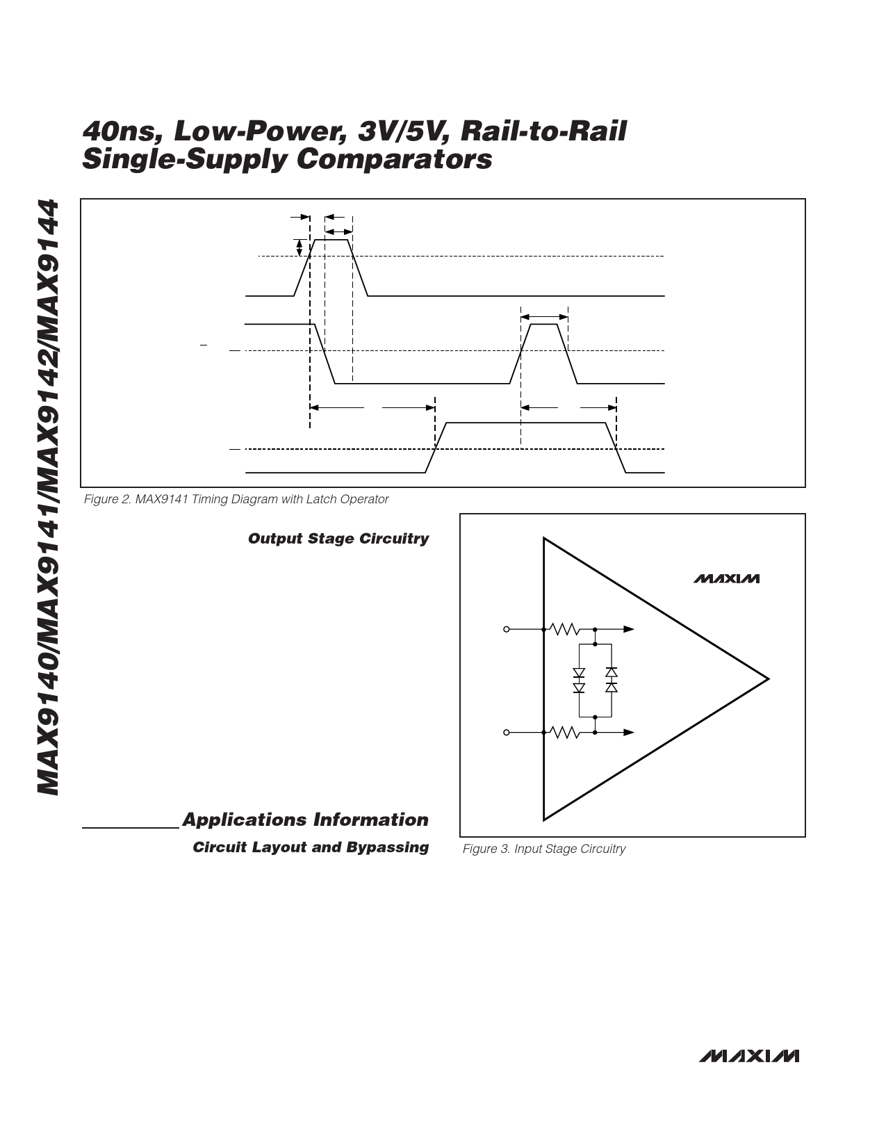
Figure 2. MAX9141 Timing Diagram with Latch Operator
Output Stage Circuitry
The MAX9140/MAX9141/MAX9142/MAX9144 contain a
current-driven output stage as shown in Figure 4.
During an output transition, ISOURCE or ISINK is pushed
or pulled to the output pin. The output source or sink
current is high during the transition, creating a rapid
slew rate. Once the output voltage reaches VOH or
VOL, the source or sink current decreases to a small
value, capable of maintaining the VOH or VOL static
condition. This significant decrease in current con-
serves power after an output transition has occurred.
One consequence of a current-driven output stage is a
linear dependence between the slew rate and the load
capacitance. A heavy capacitive load will slow down a
voltage output transition. This can be useful in noise-
sensitive applications where fast edges may cause
interference.
Applications Information
Circuit Layout and Bypassing
The high-gain bandwidth of the MAX9140/MAX9141/
MAX9142/MAX9144 requires design precautions to
realize the full high-speed capabilities of these com-
parators. The recommended precautions are:
1) Use a PCB with a good, unbroken, low-induc-
tance ground plane.
2) Place a decoupling capacitor (a 0.1µF ceramic
capacitor is a good choice) as close to VCC as
possible.
tLPW
tLPD
MAX9140
MAX9141
4.1kΩ
MAX9142
IN+
TO INTERNAL
MAX9144
CIRCUITRY
TO INTERNAL
IN–
CIRCUITRY
4.1kΩ
Figure 3. Input Stage Circuitry
3) Pay close attention to the decoupling capacitor’s
bandwidth, keeping leads short.
4) On the inputs and outputs, keep lead lengths
short to avoid unwanted parasitic feedback
around the comparators.
5) Solder the device directly to the PCB instead of
using a socket.
8 _______________________________________________________________________________________
Share Link: 