MB89945 데이터 시트보기 (PDF) - Fujitsu
부품명
상세내역
제조사
MB89945 Datasheet PDF : 38 Pages
| |||
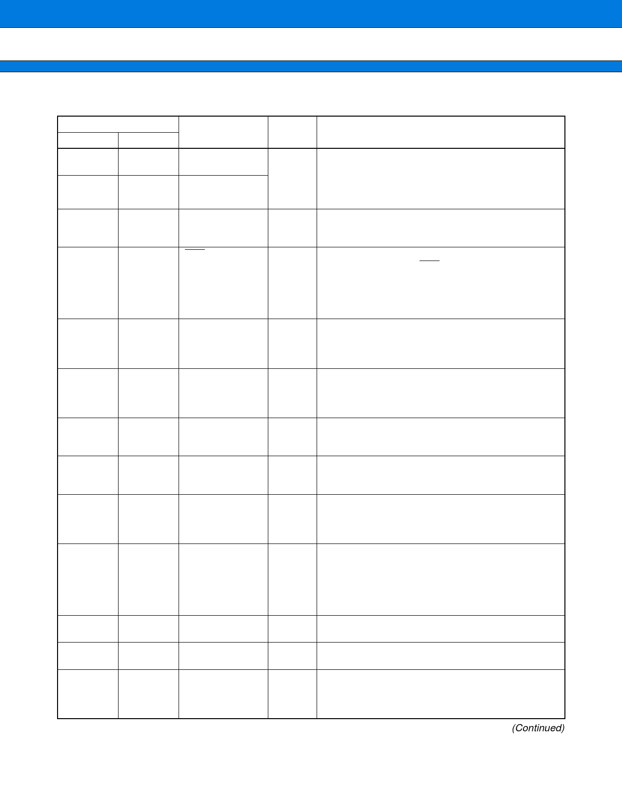
MB89940 Series
s PIN DESCRIPTION
Pin no.
QFP*1
MQFP*2
5
5
Pin name
X0
6
6
X1
48
48
MODE
2
2
RST
34 to 27
34 to 27 P00/SEG00 to
P07/SEG07
26 to 20,
18
26 to 20, P10/SEG08 to
18
P17/SEG15
17
17
P20/SEG16
16
16
P21/V0
15
15
P22/EC/V1
14
14
P23/TO/V2
13
13
P24/V3
12, 11, 10
35
12, 11, 10
35
P25/INT0 to
P27/INT2
P30/FUELO
*1: FPT-48P-M16
*2: MQP-48C-P01
6
Circuit
type
A
B
C
H
J
I
F
F
F
F
E
D
Function
Pin for connecting the crystal resonator.
X0 and X1 can be directly connected to a crystal
oscillator.
When the oscillation clock is provided to X0
externally, X1 should be left open.
The mode input is used for entering the MPU into the
test mode.
In user applications, MODE is connected to VSS.
Applying a reset pulse to this pin forces the MPU to
enter the initial state. RST is active low and drives
low state when an internal reset occurs.
Reset pulses of the duration less than the minimum
pulse width may cause the MCU to enter undefined
states.
These pins have two functions.
Their functions can be switched between Port 0 and
LCD segment signal outputs by setting the internal
registers of the LCD controller.
These pins have two functions.
Their functions can be switched between Port 1 and
LCD segment signal outputs by setting the internal
registers of the LCD controller.
This pin can be used as the bit 0 of Port 2 or an LCD
segment signal output by setting the internal register
of the LCD controller.
This pin is the bit 1 of Port 2.
This pin can also be used for an external LCD bias
voltage input.
This pin can be used as the bit 2 of Port 2 or the
external clock input for the interval timer.
This pin can also be used for an external LCD bias
voltage input.
This pin can be used as the bit 3 of Port 2 or the
output for the interval timer.
Its function can be switched by setting the internal
register of the interval timer.
This pin can also be used for an external LCD bias
voltage input.
This pin can be used as the bit 4 of Port 2 or an
external LCD bias voltage input.
These pins are used for Port 2.
They can also be used for external interrupt inputs.
This pin can be used for the bit 0 of Port 3 or the
output from PWM3.
The function of this pin can be switched by setting
the internal register of PWM3.
(Continued)
Share Link: 