MC-7833-AZ 데이터 시트보기 (PDF) - California Eastern Laboratories.
부품명
상세내역
제조사
MC-7833-AZ Datasheet PDF : 3 Pages
| |||
NEC's 870 MHz GaAs CATV
PUSH-PULL AMPLIFIER
MC-7831
MC-7832
MC-7833
FEATURES
• GaAs ACTIVE DEVICES
• LOW DISTORTION
• HIGH LINEAR GAIN:
MC-7831 - GL = 18 dB MIN at f = 870 MHz
MC-7832 - GL = 22 dB MIN at f = 870 MHz
MC-7833 - GL = 25 dB MIN at f = 870 MHz
• LOW RETURN LOSS
• LOW GAIN CHANGE OVER TEMPERATURE
• SPECIFIED FOR 79, 110, and 132 CHANNELS
PERFORMANCE
• HIGH RELIABILITY AND RUGGEDNESS:
Withstands environmental extremes as well as Silicon
devices (Surge, ESD, Etc.)
DESCRIPTION
NEC's MC-7831, MC-7832, and MC-7833 are GaAs Multi-
Chip Modules designed for use as input stages in CATV ap-
plications up to 870 MHz. The only difference between these
devices is gain, which is 18 dB, 22 dB, and 25 dB respec-
tively. Because these units are GaAs devices they have low
distortion, low noise figure, and low return loss across the entire
frequency band.
Like the previous generation of products, these devices sur-
vive such hazards as surge and ESD as well as their silicon
competitors, but deliver superior performance with low DC
current required. All devices are assembled and tested using
fully automated equipment to maximize consistency in part to
part performance, and reliability is assured by NEC's strin-
gent quality and process control procedures. These parts come
in industry compatible hybrid packages.
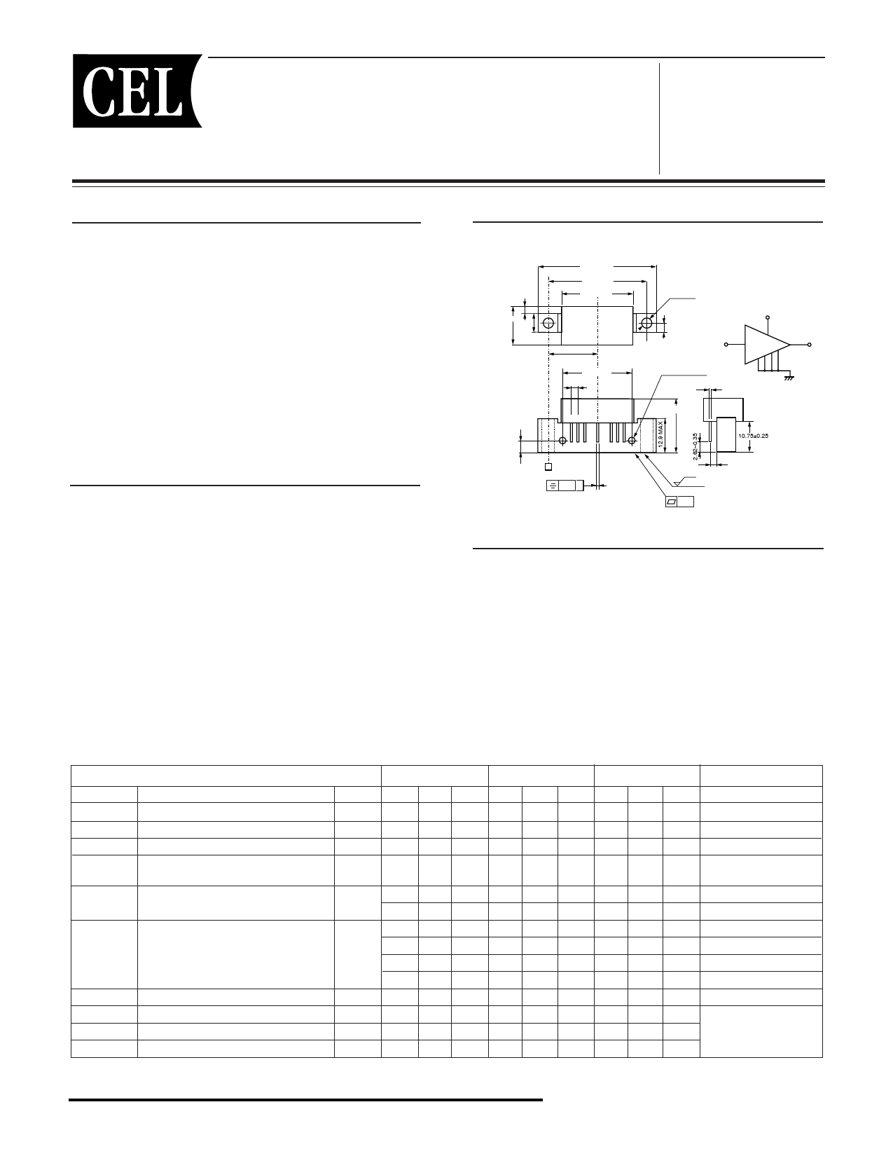
OUTLINE DIMENSIONS (Units in mm)
PACKAGE OUTLINE H02
3.2 MAX
14.85 MAX
8.1 MAX
45.08 MAX
38.1±0.25
27.5 MAX
19.05±0.38
25.4±0.25
2.54±0.25
12 3 5 789
4.19±0.13 A
0.38.. A
4.25
+
-
0.25
0.35
4.0±0.25
6-32 unc 2B
21.5 MAX
6.3 2.5
±0.05
VDD
5
1
9
In
Out
2 378
0.51±0.050
Gnd
10.75±0.25
2.54±0.38
APPLICATIONS
• CATV HEADEND SYSTEMS
• CATV OPTICAL NODES
• CATV DISTRIBUTION AMPS
ELECTRICAL CHARACTERISTICS (TA = 30±5 °C, VDD = 24 V, ZS = ZL = 75 Ω)
SYMBOLS
BW
GL
S
Gf
NF
RL
IDD
CTB
XMod
CSO
PART NUMBER
CHARACTERISTICS
Frequency Range
Linear Gain
Gain Slope
Gain Flatness
Noise Figure 1
Noise Figure 2
Input/Output Return Loss
Operating Current
Composite Triple Beat
Cross Modulation1dBc
Composite Second Order
UNITS
MHz
dB
dB
dB
dB
dB
mA
dBc
dBc
dBc
MC-7831
MIN TYP MAX
50 – 870
18.0 – 19.0
0.2 – 1.0
– – 0.7
MC-7832
MIN TYP MAX
50 – 870
22.0 – 23.0
0.6 – 1.4
– – 0.7
MC-7833
MIN TYP MAX
50 – 870
25.0 – 26.0
1.0 – 1.8
– – 0.7
– – 6.5 – – 6.0 – – 5.5
– – 7.0 – – 6.5 – – 6.0
20.0 – – 20.0 – – 20.0 – –
19.0 – – 19.0 – – 19.0 – –
17.5 – – 17.5 – – 17.5 – –
16.0 – – 16.0 – – 16.0 – –
180 – 240 180 – 240 180 – 240
– -59 -57 – -59 -57 – -59 -57
– -51 -50 – -53 -50 – -53 -50
– -63 -57 – -60 -57 – -61 -57
TEST CONDITIONS
f = 870 MHz
f = 40 to 870 MHz
40 to 870 MHz;
Peak to Valley
f = 50 MHz
f = 870 MHz
40 to 160MHz
160 to 320 MHz
320 to 640 MHz
640 to 870 MHz
RF OFF
f = 40 to 870 MHz
110 Channels,
VOUT = 44 dBmV, Flat
1. Measured per US standard methods and procedures (using selective level meter).
California Eastern Laboratories
Share Link: 