MC10E1651FNR2 데이터 시트보기 (PDF) - ON Semiconductor
부품명
상세내역
제조사
MC10E1651FNR2 Datasheet PDF : 10 Pages
| |||
MC10E1651
5V, −5V Dual ECL Output
Comparator with Latch
The MC10E1651 is fabricated using ON Semiconductor’s
advanced MOSAIC III™ process. The MC10E1651 incorporates a
fixed level of input hysteresis as well as output compatibility with 10
KH logic devices. In addition, a latch is available allowing a sample
and hold function to be performed. The device is available in both a
16-pin DIP and a 20-pin surface mount package.
The latch enable (LENa and LENb) input pins operate from standard
ECL 10 KH logic levels. When the latch enable is at a logic high level,
the MC10E1651 acts as a comparator; hence, Q will be at a logic high
level if V1 > V2 (V1 is more positive than V2). Q is the complement
of Q. When the latch enable input goes to a low logic level, the outputs
are latched in their present state providing the latch enable setup and
hold time constraints are met.
Features
• Typical 3.0 dB Bandwidth > 1.0 GHz
• Typical V to Q Propagation Delay of 775 ps
• Typical Output Rise/Fall of 350 ps
• Common Mode Range −2.0 V to +3.0 V
• Individual Latch Enables
• Differential Outputs
• 28 mV Input Hysteresis
• Operating Mode: VCC = 5.0 V, VEE = −5.2 V, GND = 0 V
• No Internal Input Pulldown Resistors
• ESD Protection: > 2 kV Human Body Model,
> 100 V Machine Model
• Meets or Exceeds JEDEC Spec EIA/JESD78 IC Latchup Test
• Moisture Sensitivity Level 1
For Additional Information, see Application Note AND8003/D
• Flammability Rating: UL 94 V−0 @ 0.125 in,
Oxygen Index: 28 to 34
• Transistor Count = 85 devices
• Pb−Free Packages are Available*
http://onsemi.com
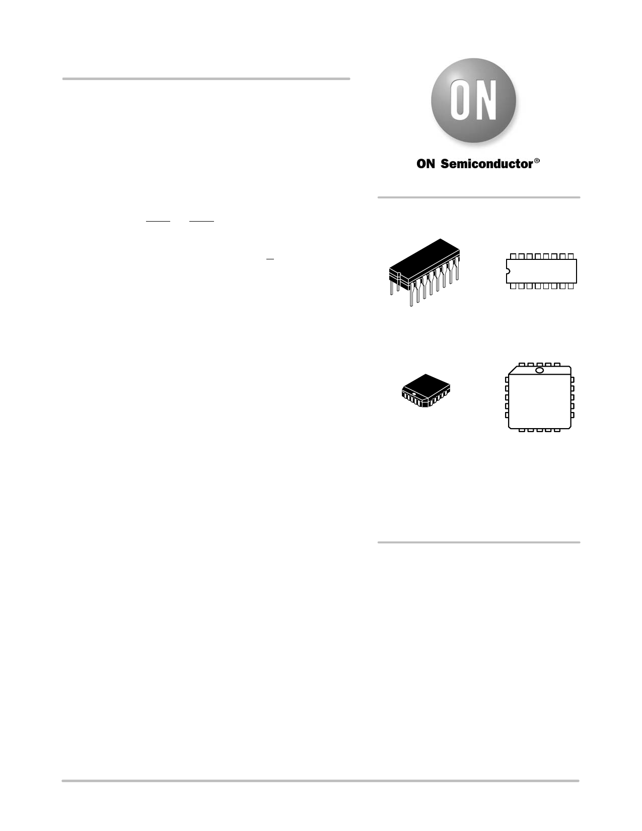
MARKING
DIAGRAMS
16
MC10E1651L
AWLYYWW
1
CDIP−16
L SUFFIX
CASE 620A
1 20
20 1
PLCC−20
FN SUFFIX
CASE 775
MC10E
1651FNG
AWLYYWW
A
= Assembly Location
WL = Wafer Lot
YY
= Year
WW = Work Week
G
= Pb−Free Package
ORDERING INFORMATION
See detailed ordering and shipping information in the package
dimensions section on page 7 of this data sheet.
*For additional information on our Pb−Free strategy and soldering details, please
download the ON Semiconductor Soldering and Mounting Techniques
Reference Manual, SOLDERRM/D.
© Semiconductor Components Industries, LLC, 2006
1
November, 2006 − Rev. 8
Publication Order Number:
MC10E1651/D
Share Link: 