MC10H188MEL 데이터 시트보기 (PDF) - ON Semiconductor
부품명
상세내역
제조사
MC10H188MEL Datasheet PDF : 6 Pages
| |||
MC10H188
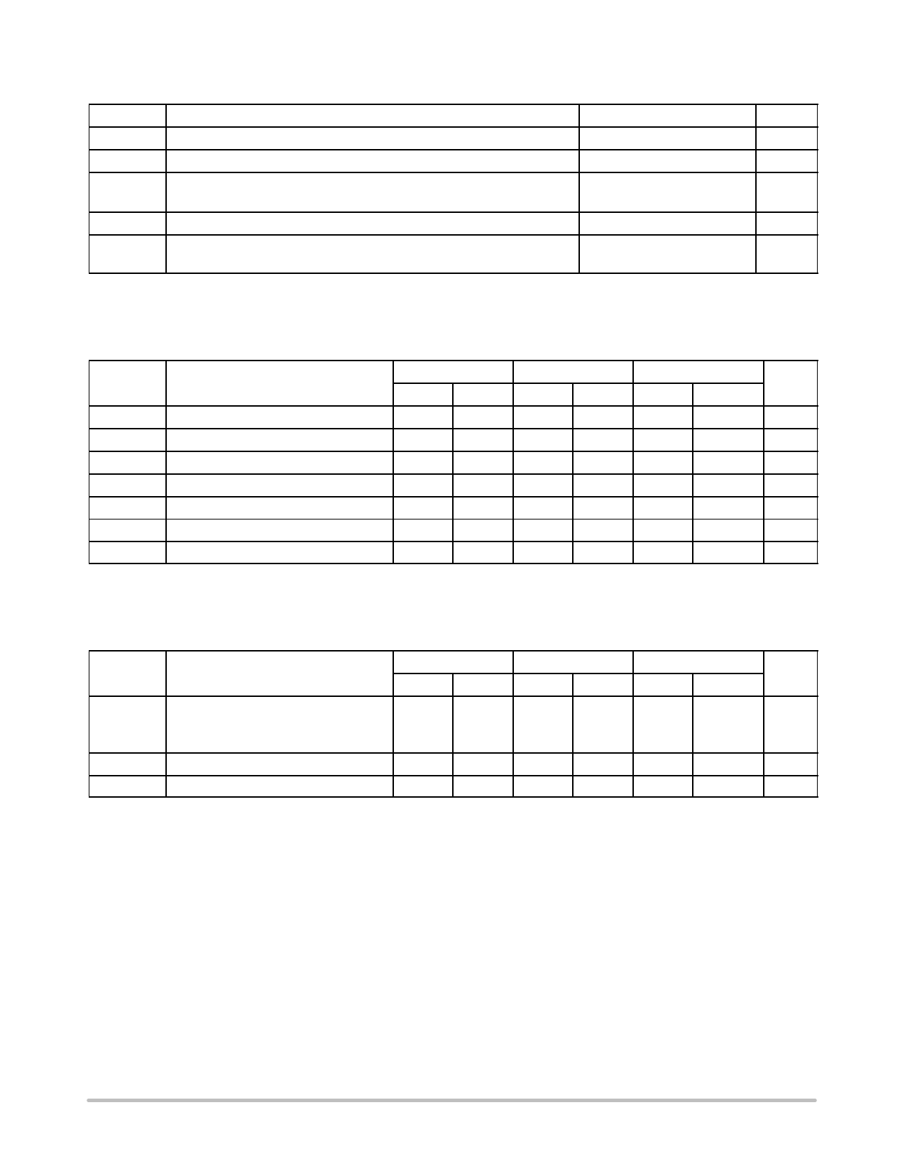
Table 1. MAXIMUM RATINGS
Symbol
Characteristic
Rating
Unit
VEE
Power Supply (VCC = 0)
VI
Input Voltage (VCC = 0)
Iout
Output Current − Continuous
− Surge
−8.0 to 0
Vdc
0 to VEE
Vdc
50
mA
100
TA
Operating Temperature Range
Tstg
Storage Temperature Range − Plastic
− Ceramic
0 to +75
°C
−55 to +150
°C
−55 to +165
°C
Maximum ratings are those values beyond which device damage can occur. Maximum ratings applied to the device are individual stress limit
values (not normal operating conditions) and are not valid simultaneously. If these limits are exceeded, device functional operation is not implied,
damage may occur and reliability may be affected.
Table 2. ELECTRICAL CHARACTERISTICS (VEE = −5.2 V ±5%) (Note )
0°
25°
75°
Symbol
Characteristic
Min
Max
Min
Max
Min
Max
Unit
IE
Power Supply Current
−
46
−
42
−
46
mA
IinH
Input Current High
−
495
−
310
−
310
mA
IinL
Input Current Low
0.5
−
0.5
−
0.3
−
mA
VOH
High Output Voltage
−1.02 −0.84 −0.98 −0.81 −0.92
−0.735
Vdc
VOL
Low Output Voltage
−1.95 −1.63 −1.95 −1.63 −1.95
−1.60
Vdc
VIH
High Input Voltage
−1.17 −0.84 −1.13 −0.81 −1.07
−0.735
Vdc
VIL
Low Input Voltage
−1.95 −1.48 −1.95 −1.48 −1.95
−1.45
Vdc
1. Each MECL 10H series circuit has been designed to meet the dc specifications shown in the test table, after thermal equilibrium has been
established. The circuit is in a test socket or mounted on a printed circuit board and transverse air flow greater than 500 lfpm is maintained.
Outputs are terminated through a 50 W resistor to −2.0 V.
Table 3. AC PARAMETERS
0°
25°
75°
Symbol
Characteristic
Min
Max
Min
Max
Min
Max
Unit
tpd
Propagation Delay
Enable
Data
ns
0.7
2.2
0.7
2.2
0.7
2.2
0.7
1.9
0.7
1.9
0.7
1.9
tr
Rise Time
tf
Fall Time
0.7
2.4
0.7
2.4
0.7
2.4
ns
0.7
2.4
0.7
2.4
0.7
2.4
ns
NOTE: Device will meet the specifications after thermal equilibrium has been established when mounted in a test socket or printed circuit
board with maintained transverse airflow greater than 500 lfpm. Electrical parameters are guaranteed only over the declared
operating temperature range. Functional operation of the device exceeding these conditions is not implied. Device specification limit
values are applied individually under normal operating conditions and not valid simultaneously.
http://onsemi.com
2
Share Link: 