MC1495D 데이터 시트보기 (PDF) - ON Semiconductor
부품명
상세내역
제조사
MC1495D Datasheet PDF : 20 Pages
| |||
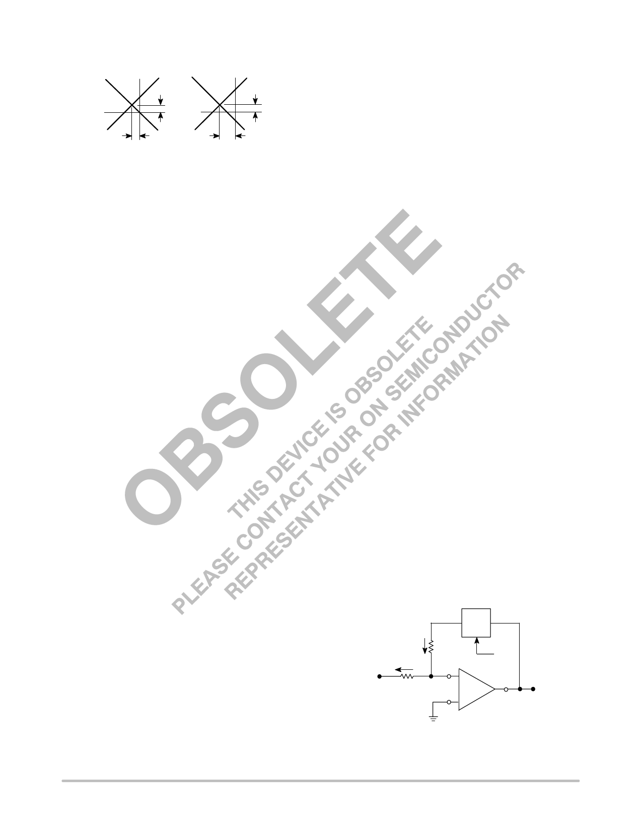
MC1495
X, Y and Output Offset Voltages
VO
Output
Offset
VO
Output
Offset
Vx
Vy
X Offset
Y Offset
For most dc applications, all three offset adjust
potentiometers (P1, P2, P4) will be necessary. One or more
offset adjust potentiometers can be eliminated for ac
applications (see Figures 28, 29, 30, 31).
If well regulated supply voltages are available, the offset
adjust circuit of Figure 13 is recommended. Otherwise, the
circuit of Figure 14 will greatly reduce the sensitivity to
power supply changes.
Scale Factor
The scale factor K is set by P3 (Figure 21). P3 varies I3
which inversely controls the scale factor K. It should be
noted that current I3 is one-half the current through R1. R1
sets the bias level for Q5, Q6, Q7, and Q8 (see Figure 3).
Therefore, to be sure that these devices remain active under
all conditions of input and output swing, care should be
exercised in adjusting P3 over wide voltage ranges (see
General Design Procedure).
Adjustment Procedures
The following adjustment procedure should be used to
null the offsets and set the scale factor for the multiply mode
of operation, (see Figure 21).
1. X-Input Offset
(a) Connect oscillator (1.0 kHz, 5.0 Vpp sinewave)
to the Y-input (Pin 4).
(b) Connect X-input (Pin 9) to ground.
(c) Adjust X offset potentiometer (P2) for an ac
null at the output.
2. Y-Input Offset
(a) Connect oscillator (1.0 kHz, 5.0 Vpp sinewave)
to the X-input (Pin 9).
(b) Connect Y-input (Pin 4) to ground.
(c) Adjust Y offset potentiometer (P1) for an ac null
at the output.
3. Output Offset
(a) Connect both X and Y-inputs to ground.
(b) Adjust output offset potentiometer (P4) until
the output voltage (VO) is 0 Vdc.
4. Scale Factor
(a) Apply +10 Vdc to both the X and Y-inputs.
(b) Adjust P3 to achieve + 10 V at the output.
5. Repeat steps 1 through 4 as necessary.
The ability to accurately adjust the MC1495 depends upon
the characteristics of potentiometers P1 through P4.
Multi-turn, infinite resolution potentiometers with low
temperature coefficients are recommended.
DC APPLICATIONS
Multiply
The circuit shown in Figure 21 may be used to multiply
signals from dc to 100 kHz. Input levels to the actual
multiplier are 5.0 V (max). With resistive voltage dividers
the maximum could be very large however, for this
application two-to-one dividers have been used so that the
maximum input level is 10 V. The maximum output level
has also been designed for 10 V (max).
Squaring Circuit
If the two inputs are tied together, the resultant function is
squaring; that is VO = KV2 where K is the scale factor. Note
that all error terms can be eliminated with only three
adjustment potentiometers, thus eliminating one of the input
offset adjustments. Procedures for nulling with adjustments
are given as follows:
A. AC Procedure:
1. Connect oscillator (1.0 kHz, 15 Vpp) to input.
2. Monitor output at 2.0 kHz with tuned voltmeter
and adjust P3 for desired gain. (Be sure to peak
response of the voltmeter.)
3. Tune voltmeter to 1.0 kHz and adjust P1 for a
minimum output voltage.
4. Ground input and adjust P4 (output offset) for
0 Vdc output.
5. Repeat steps 1 through 4 as necessary.
B. DC Procedure:
1. Set VX = VY = 0 V and adjust P4 (output offset
potentiometer) such that VO = 0 Vdc
2. Set VX = VY = 1.0 V and adjust P1 (Y-input offset
potentiometer) such that the output voltage is
+ 0.100 V.
3. Set VX = VY = 10 Vdc and adjust P3 such that
the output voltage is + 10 V.
4. Set VX = VY = −10 Vdc. Repeat steps 1 through
3 as necessary.
KVX VY
X
I1 R1
VX
I2
VZ
−
R2
VY
+
Figure 24. Basic Divide Circuit
http://onsemi.com
11
Share Link: 