MC33348 데이터 시트보기 (PDF) - ON Semiconductor
부품명
상세내역
제조사
MC33348 Datasheet PDF : 15 Pages
| |||
MC33348
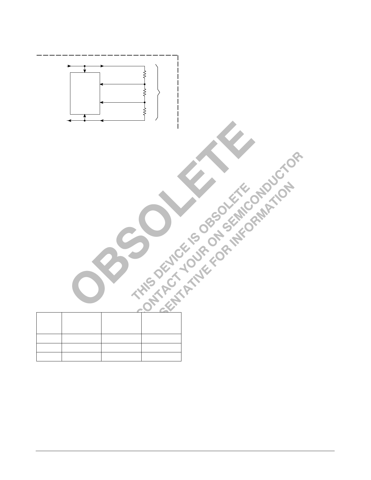
Figure 10. Cell Voltage Limit Sampling
From
Cell Voltage
Sample Switch
Over/Under
Cell Voltage
Detector
&
Reference
Cell Voltage
Discharge Voltage R1
Threshold
+
Charge Voltage
Threshold
R2
Cell
Voltage
−
To
Cell Negative
Terminal
Cell Voltage
R3
Return
The cell charge and discharge voltage limits are controlled by the
values selected for the internal resistor divider string and the
comparator input threshold. As the battery pack reaches full charge,
the Cell Voltage Detector will sense an overvoltage fault condition
when the cell exceeds the designed overvoltage limit. The fault
information is stored in a data latch and charge MOSFET Q1 is turned
off, disconnecting the battery pack from the charging source. An
internal current source pull−up is then applied to lower tap of the
divider, creating a hysteresis voltage. As a result of an overvoltage
fault, the battery pack is available for discharging only.
The overvoltage fault is reset by applying a load to the battery pack.
As the voltage across the cell falls below the hysteresis level, charge
MOSFET Q1 will turn on and the current source pull−up will turn off.
The battery pack will now be available for charging or discharging.
As the load eventually depletes the battery pack charge, the Cell
Voltage Detector will sense an undervoltage fault condition when the
cell falls below the designed undervoltage limit. After three
consecutive faults are detected, discharge MOSFET Q2 is turned off,
disconnecting the battery pack from the load. The protection circuit
will now enter a low current sleepmode state. Refer to Figure 6. As a
result of the undervoltage fault, the battery pack is available for
charging only. The typical cutoff thresholds and hysteresis voltage are
shown in Figure 11.
Figure 11. Cutoff and Hysteresis Limits
ÁÁÁÁÁÁÁÁÁÁÁÁÁÁÁÁÁ Device
ÁÁÁÁÁÁÁÁÁÁÁÁÁÁÁÁÁ Suffix
Charging
Cutoff
(V)
Hysteresis
(mV)
Disharging
Cutoff
(V)
ÁÁÁÁÁÁÁÁÁÁÁÁÁÁÁÁÁ −1, −2
4.20
300
2.25
ÁÁÁÁÁÁÁÁÁÁÁÁÁÁÁÁÁ −3, −4
4.25
300
2.28
ÁÁÁÁÁÁÁÁÁÁÁÁÁÁÁÁÁÁÁÁÁÁÁÁÁÁÁÁÁÁÁÁÁÁ −5, −6
4.35
300
2.30
The undervoltage logic is designed to automatically reset if less
than three consecutive faults appear. This helps to prevent a
premature disconnection of the load during high current pulses when
the battery pack charge is close to being depleted.
The undervoltage fault is reset by applying charge current to the
battery pack. When the voltage on Pin 3 exceeds Pin 5 by 0.6 V,
discharge MOSFET Q2 will turn on. The battery pack will now be
available for charging or discharging.
http://onsemi.com
10
Share Link: 