MC33690 데이터 시트보기 (PDF) - Freescale Semiconductor
부품명
상세내역
제조사
MC33690 Datasheet PDF : 26 Pages
| |||
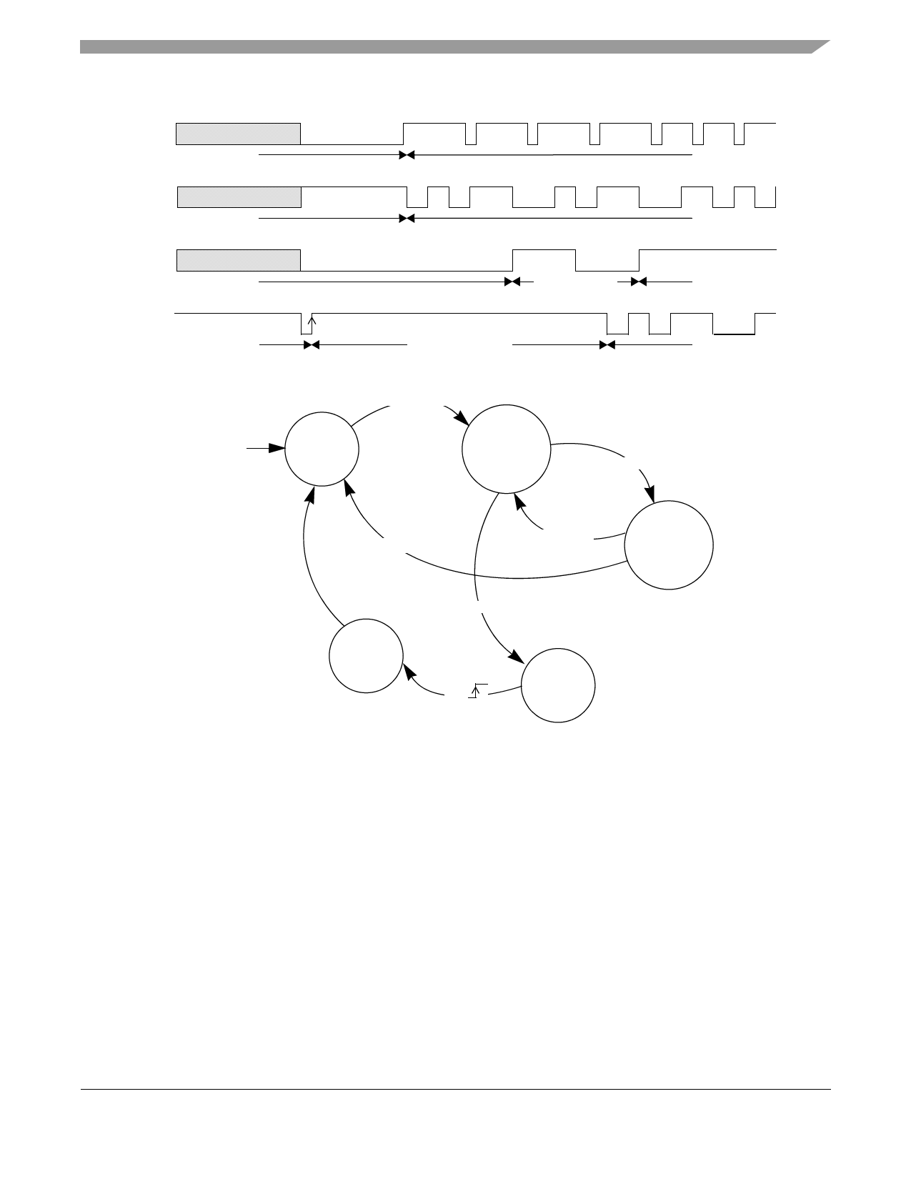
Standalone Configuration with One-Wire Bus
Read to write mode:
K line
read mode
Write to read mode:
T0 £ t < T0’+T1’
1
1
1
0
0
0
write mode
K line
write mode
Write to standby mode:
t ŠT0
read mode
K line
write mode
Standby mode to read mode:
t Š T1
T2
T2
acknowledge
standby mode
K line
standby mode
wake-up sequence
read mode
Figure 6. Mode Access Description in One-Wire Bus Configuration
Reset
T0 £ K line low
Read
Write
TD1/2 off
K line high < T0’
T0 £ K line high
K line low
T1 £ K line low
write
TD1/2
switching
Wake-up
K
Standby
Figure 7. Configuration A State Diagram
7.1 Timing Definitions for a 8 MHz Crystal
The timing definitions for a 8 MHz crystal are:
• Tref is crystal oscillator period (125 ns typ.)
• T0=8064.Tref = 1.008ms typ.
• T0’=7932.Tref = 0.992ms typ.
• T1=16256.Tref = 2.032ms typ.
• T1’=16128.Tref = 2.016ms typ.
• T2=4096.Tref, = 512µs typ.
T0 is the minimum time required to guarantee the device toggles from read to write (or from write to read). However, the STARC
may toggle from read to write (or from write to read) between T0 and T0’.
T1 is the minimum time required to guarantee the device toggles from write to standby. However, the STARC may toggle in
standby between T1 and T1’.
MC33690 Standalone Tag Reader Circuit, Rev. 5
Freescale Semiconductor
11
Share Link: 