MGA-52543 데이터 시트보기 (PDF) - HP => Agilent Technologies
부품명
상세내역
제조사
MGA-52543 Datasheet PDF : 15 Pages
| |||
MGA-52543 Absolute Maximum Ratings[1]
Symbol Parameter
Units
Vd
Maximum Input Voltage
V
Vd
Supply Voltage
V
Pd
Power Dissipation[2,3]
mW
Pin
CW RF Input Power
dBm
Tj
Junction Temperature
°C
TSTG
Storage Temperature
°C
Absolute Maximum
±0.5
7.0
425
+20
160
-65 to 150
Thermal Resistance:[2]
θjc = 150°C/W
Notes:
1. Operation of this device in excess of any of
these limits may cause permanent damage.
2. Tcase = 25°C
Electrical Specifications
Tc = +25°C, Zo = 50 Ω, Vd = 5V, unless noted
Symbol
Parameter and Test Condition
Frequency
Units Min. Typ.
Max. σ [3]
Id test
NF [1]
Gain [1]
IIP3 [1]
Fmin[2]
Ga[2]
OIP3 [1]
P1dB [1]
RLin[1]
RL out [1]
ISOL [1]
Current drawn
Noise Figure
Gain
Input Third Order Intercept Point
Minimum Noise Figure
Associated Gain at Fmin
Output Third Order Intercept Point
Output Power at 1 dB Gain Compression
Input Return Loss
Output Return Loss
Isolation |s12|2
N/A
1.9 GHz
0.9 GHz
1.9 GHz
0.9 GHz
1.9 GHz
0.9 GHz
1.9 GHz
0.9 GHz
1.9 GHz
0.9 GHz
1.9 GHz
0.9 GHz
1.9 GHz
0.9 GHz
1.9 GHz
0.9 GHz
1.9 GHz
0.9 GHz
1.9 GHz
0.9 GHz
mA
45
dB
dB
13
dBm
14
dB
dB
dBm
dBm
dB
dB
dB
53
65
3.57
1.9
2.3
0.15
1.8
14.2
15.5
0.26
15
+17.5
2.28
+18
1.6
1.5
15.0
16.2
31.7
33.0
+17.4
+18
11
15
20
22
-25
-25
Notes:
1. Measurements obtained from a fixed narrow band tuning described in Figure 1. This circuit designed to optimize Noise Figure and IIP3 while
maintaining VSWR better than 2:1.
2. Minimum Noise Figure and Associated Gain at Fmin computed from S-parameter and Noise Parameter data measured in an automated NF system.
3. Standard deviation data are based on at least 400 part sample size and 11 wafer lots.
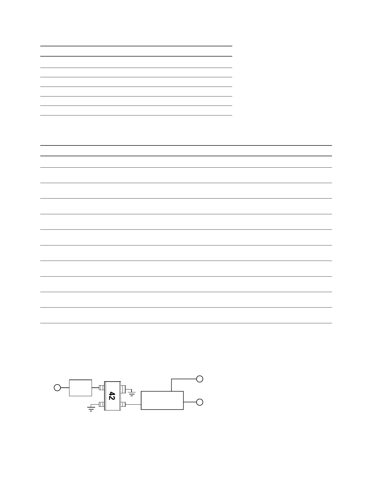
RF
Input
Input
Match
Output Match
and DC Bias
Vd
RF
Output
Figure 1. Block Diagram of Test Fixture.
See Figure 7 in the Applications section for an equivalent schematic of 1.9 GHz circuit; Figure 11 in the Applications section for 900 MHz circuit.
2
Share Link: 