MLX90129 데이터 시트보기 (PDF) - Melexis Microelectronic Systems
부품명
상세내역
제조사
MLX90129 Datasheet PDF : 60 Pages
| |||
MLX90129
13.56MHZ SENSOR TAG / DATALOGGER IC
Address
#12
#13
Description
Sensors common configuration space
Sensor power configuration word
(reserved)
Page 46
#14
Sensor trimming configuration word
Sensor 0 configuration space
#15
Sensor 0: Sensor control word
#16
Sensor 0: Sensor low threshold word
#17
Sensor 0: Sensor high threshold word
#18
Sensor 0: Sensor signal conditioner configuration word
#19
Sensor 0: Sensor connections configuration word
#1A
Sensor 0: Sensor resistance configuration word
Sensor 1 configuration space
#1B
Sensor 1: Sensor control word
#1C
Sensor 1: Sensor low threshold word
#1D
Sensor 1: Sensor high threshold word
#1E
Sensor 1: Sensor signal conditioner configuration word
#1F
Sensor 1: Sensor connections configuration word
#20
Sensor 1: Sensor resistance configuration word
Sensor 2 configuration space
#21
Sensor 2: Sensor control word
#22
Sensor 2: Sensor low threshold word
#23
Sensor 2: Sensor high threshold word
#24
Sensor 2: Sensor signal conditioner configuration word
#25
Sensor 2: Sensor connections configuration word
#26
Sensor 2: Sensor resistance configuration word
EE-Latches backup space
#27
Internal device backup word 1
#28
Internal device backup word 2
Page 46
Page 48
Page 48
Page 48
Page 48
Page 48
Page 48
Page 48
Page 48
Page 48
Page 48
Page 48
Page 48
Page 48
Page 48
Page 48
Page 48
Page 48
Page 48
Page 16
Page 16
(**) In the register file, this configuration space is updated from the appropriate part of the Extended sensor configuration space
at each access to one of the three sensors. This configuration space and all others with higher addresses are not updated during
a Register File Update operation.
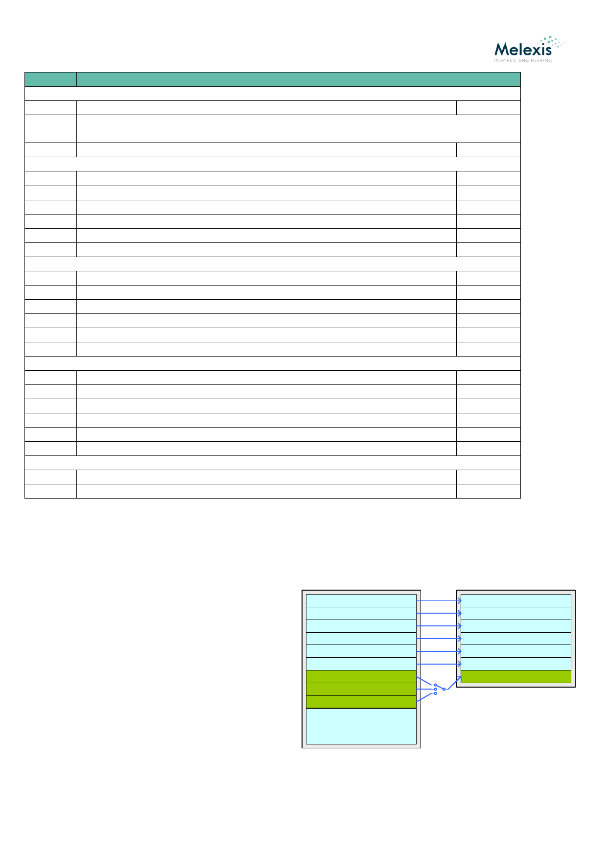
7.4.2. Update of the Register File
The EEPROM contains the initial image of the Register File.
This image is copied after the power-on, upon a SPI / RFID
Update request. The sensor configuration in the Register File
depends on the currently selected sensor. The sensor is
selected either manually by reading the ADC buffer
corresponding or automatically during a standalone
application.
EEPROM
UID
Security configuration
DMA configuration
RFID configuration
Master SPI configuration
Time & Power management
Sensor 0 configuration
Sensor 1 configuration
Sensor 2 configuration
USER: 3.4 kbit space
REGISTER FILE
UID
Security configuration
DMA configuration
RFID configuration
Master SPI configuration
Time & Power management
Selected Sensor configuration
Update command
or Power On
or Read ADC buffer
command
REVISION 011 - JUNE 13, 2017
3901090129
Page 18 of 60
Share Link: 