MM1381 데이터 시트보기 (PDF) - Mitsumi
부품명
상세내역
제조사
MM1381 Datasheet PDF : 10 Pages
| |||
MITSUMI
RGB Video Amplifier with OSD Input MM1381, 1382, 1383
Pin Description
Pin no.
1
2
3
Pin name
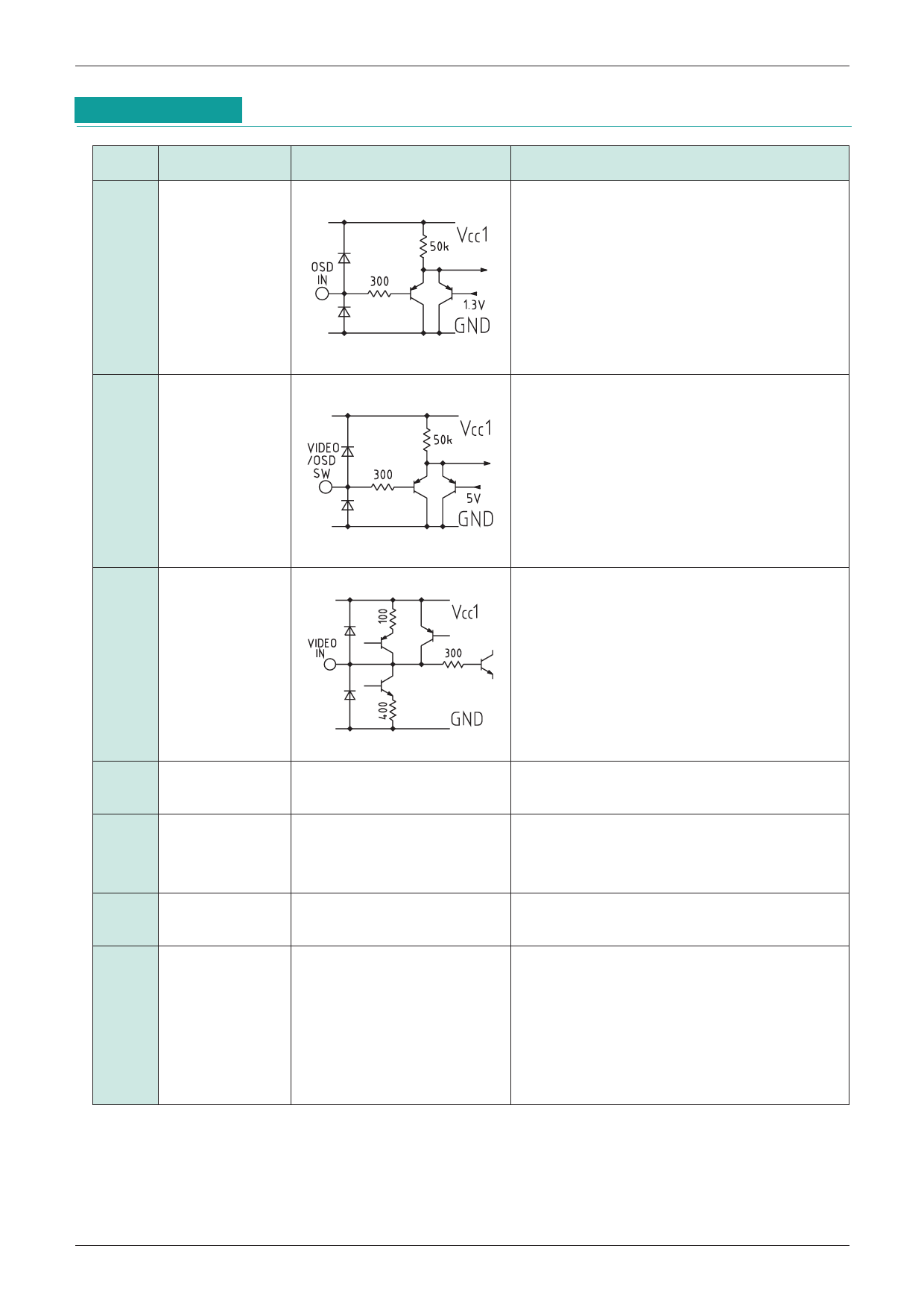
R OSD IN
G OSD IN
B OSD IN
Internal equivalent circuit diagram
Pin Description
These inputs accept standard TTL input. Each
color is either completely ON (logic high) or
completely OFF (logic low). Connect unused
pins to ground with a 47kΩ resistor.
4
VIDEO/OSD
SWITCH
This input accepts standard TTL input.
H : OSD, L : VIDEO
Connect OSD to ground with a 47kΩ resistor
when not in use.
5
R VIDEO IN
8
G VIDEO IN
11
B VIDEO IN
6
VCC1
9
7
GND
10
21
12
VREF
13 VIDEO CONTRAST
14 OSD CONTRAST
26
B DRIVE
27
G DRIVE
28
R DRIVE
Video inputs.
These inputs must be AC coupled using a
capacitor of at least 1µF. The ideal capacitance
is 10 (F. DC playback is done with these
inputs. Also, serial resistor of approximately
33Ω must be used.
Power supply pin (except for output stage).
GND pins.
The GND pins are all connected internally, and
must be connected on the board as well.
Used for internal reference additional filter
capacitor. Voltage of this pin is 2.0V.
Contrast control pin :
4V no attenuation
0V attenuation over 60dB
Drive control pin :
4V no attenuation
0V 12dB attenuation
Share Link: 