MMBTA55LT1G 데이터 시트보기 (PDF) - ON Semiconductor
부품명
상세내역
제조사
MMBTA55LT1G Datasheet PDF : 5 Pages
| |||
MMBTA55L Series, MMBTA56L Series, SMMBTA56L Series
ELECTRICAL CHARACTERISTICS (TA = 25°C unless otherwise noted)
Characteristic
Symbol
Min
Max
Unit
OFF CHARACTERISTICS
Collector −Emitter Breakdown Voltage (Note 3)
(IC = −1.0 mAdc, IB = 0)
MMBTA55
MMBTA56, SMMBTA56
V(BR)CEO
Vdc
−60
−
−80
−
Emitter −Base Breakdown Voltage
(IE = −100 mAdc, IC = 0)
Collector Cutoff Current
(VCE = −60 Vdc, IB = 0)
Collector Cutoff Current
(VCB = −60 Vdc, IE = 0)
MMBTA55
(VCB = −80 Vdc, IE = 0)
MMBTA56, SMMBTA56
V(BR)EBO
ICES
ICBO
−4.0
−
−
−
−
−0.1
−0.1
−0.1
Vdc
mAdc
mAdc
ON CHARACTERISTICS
DC Current Gain
(IC = −10 mAdc, VCE = −1.0 Vdc)
(IC = −100 mAdc, VCE = −1.0 Vdc)
Collector −Emitter Saturation Voltage
(IC = −100 mAdc, IB = −10 mAdc)
Base −Emitter On Voltage
(IC = −100 mAdc, VCE = −1.0 Vdc)
SMALL− SIGNAL CHARACTERISTICS
hFE
−
100
−
100
−
VCE(sat)
−
Vdc
−0.25
VBE(on)
−
Vdc
−1.2
Current −Gain − Bandwidth Product (Note 4)
(IC = −100 mAdc, VCE = −1.0 Vdc, f = 100 MHz)
fT
MHz
50
−
Product parametric performance is indicated in the Electrical Characteristics for the listed test conditions, unless otherwise noted. Product
performance may not be indicated by the Electrical Characteristics if operated under different conditions.
3. Pulse Test: Pulse Width v 300 ms, Duty Cycle v 2.0%.
4. fT is defined as the frequency at which |hfe| extrapolates to unity.
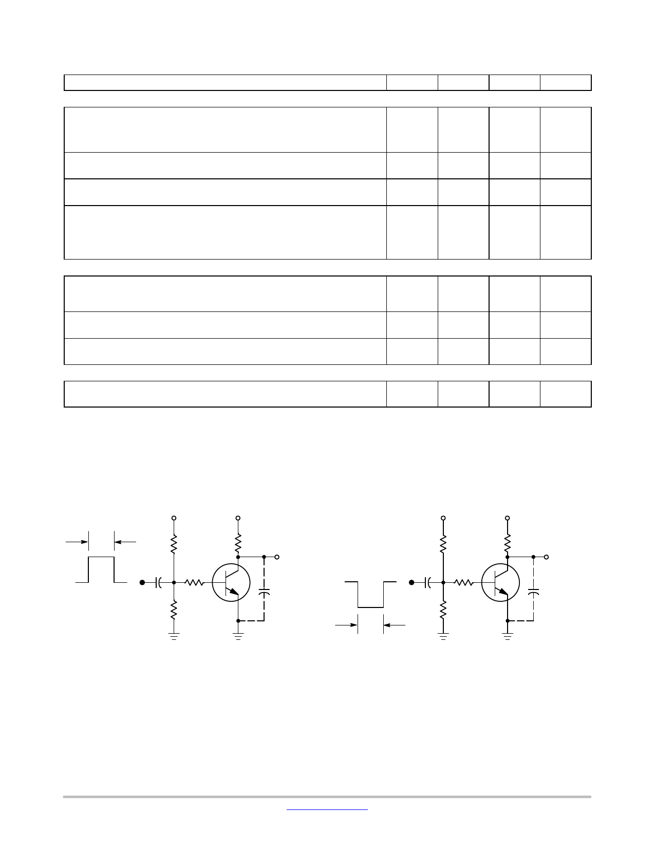
TURN-ON TIME
-1.0 V
VCC
+40 V
TURN-OFF TIME +VBB
VCC
+40 V
5.0 ms
+10 V
0
tr = 3.0 ns
100
Vin
RB
5.0 mF
100
RL
OUTPUT
* CS t 6.0 pF
5.0 ms
tr = 3.0 ns
100
Vin
RB
5.0 mF
100
RL
OUTPUT
* CS t 6.0 pF
*Total Shunt Capacitance of Test Jig and Connectors For PNP Test Circuits, Reverse All Voltage Polarities
Figure 1. Switching Time Test Circuits
www.onsemi.com
2
Share Link: 