MSG36E41 데이터 시트보기 (PDF) - Panasonic Corporation
부품명
상세내역
제조사
MSG36E41 Datasheet PDF : 7 Pages
| |||
MSG36E41
■ Electrical Characteristics (continued) Ta = 25°C ± 3°C
• Tr2
Parameter
Symbol
Collector-base cutoff current (Emitter open)
Collector-emitter cutoff current (Base open)
Emitter-base cutoff current (Collector open)
Forward current transfer ratio
Transition frequency *
Forward transfer gain *
Noise figure *
ICBO
ICEO
IEBO
hFE
fT
S21e2
NF
Collector output capacitance
Cob
(Common base, input open circuited) *
Conditions
VCB = 9 V, IE = 0
VCE = 6 V, IB = 0
VEB = 1 V, IC = 0
VCE = 3 V, IC = 3 mA
VCE = 3 V, IC = 10 mA, f = 2 GHz
VCE = 3 V, IC = 10 mA, f = 2 GHz
VCE = 3 V, IC = 3 mA, f = 2 GHz
VCB = 3 V, IE = 0, f = 1 MHz
Min Typ Max Unit
1
µA
1
µA
1
µA
100
220
19
GHz
9.0 11.0
dB
1.4 2.0
dB
0.3 0.6
pF
Note) 1. Measuring methods are based on JAPANESE INDUSTRIAL STANDARD JIS C 7030 measuring methods for transistors.
2. Observe precautions for handling. Electrostatic sensitive devices.
3. *: Verified by random sampling
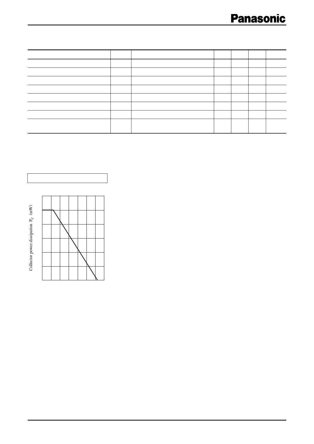
Common characteristics chart
PC Ta
120
100
80
60
40
20
0
0
40
80
120
Ambient temperature Ta (°C)
2
SJC00319BED
Share Link: 