MUR260 데이터 시트보기 (PDF) - ON Semiconductor
부품명
상세내역
제조사
MUR260 Datasheet PDF : 5 Pages
| |||
MUR260
Preferred Device
SWITCHMODEt
Power Rectifier
These state−of−the−art devices are designed for use in switching
power supplies, inverters and as free wheeling diodes.
Features
• Ultrafast 50 Nanosecond Recovery Times
• 175°C Operating Junction Temperature
• Low Forward Voltage
• Low Leakage Current
• High Temperature Glass Passivated Junction
• These are Pb−Free Devices*
http://onsemi.com
ULTRAFAST RECTIFIER
2.0 AMPERES, 600 VOLTS
Mechanical Characteristics:
• Case: Epoxy, Molded
• Weight: 0.4 Gram (Approximately)
• Finish: All External Surfaces Corrosion Resistant and Terminal
Leads are Readily Solderable
• Lead Temperature for Soldering Purposes:
260°C Max. for 10 Seconds
• Shipped in Plastic Bags; 1,000 per Bag
• Available Tape and Reel; 5,000 per Reel, by Adding a “RL’’ Suffix to
the Part Number
MAXIMUM RATINGS
Rating
Symbol Value Unit
Peak Repetitive Reverse Voltage
Working Peak Reverse Voltage
DC Blocking Voltage
VRRM
600
V
VRWM
−
VR
Average Rectified Forward Current (Note 1)
IF(AV)
2.0 @
A
(Square Wave Mounting Method #3 Per Note 3)
TA = 60°C
Non-Repetitive Peak Surge Current
(Surge applied at rated load conditions,
halfwave, single phase, 60 Hz)
IFSM
35
A
Operating Junction Temperature and Storage TJ, Tstg −65 to °C
Temperature Range
+175
THERMAL CHARACTERISTICS
Characteristics
Symbol Value Unit
Maximum Thermal Resistance,
Junction−to−Ambient
RqJA
See °C/W
Note 3
Stresses exceeding Maximum Ratings may damage the device. Maximum
Ratings are stress ratings only. Functional operation above the Recommended
Operating Conditions is not implied. Extended exposure to stresses above the
Recommended Operating Conditions may affect device reliability.
1. Pulse Test: Pulse Width = 300 ms, Duty Cycle ≤ 2.0%.
*For additional information on our Pb−Free strategy and soldering details, please
download the ON Semiconductor Soldering and Mounting Techniques
Reference Manual, SOLDERRM/D.
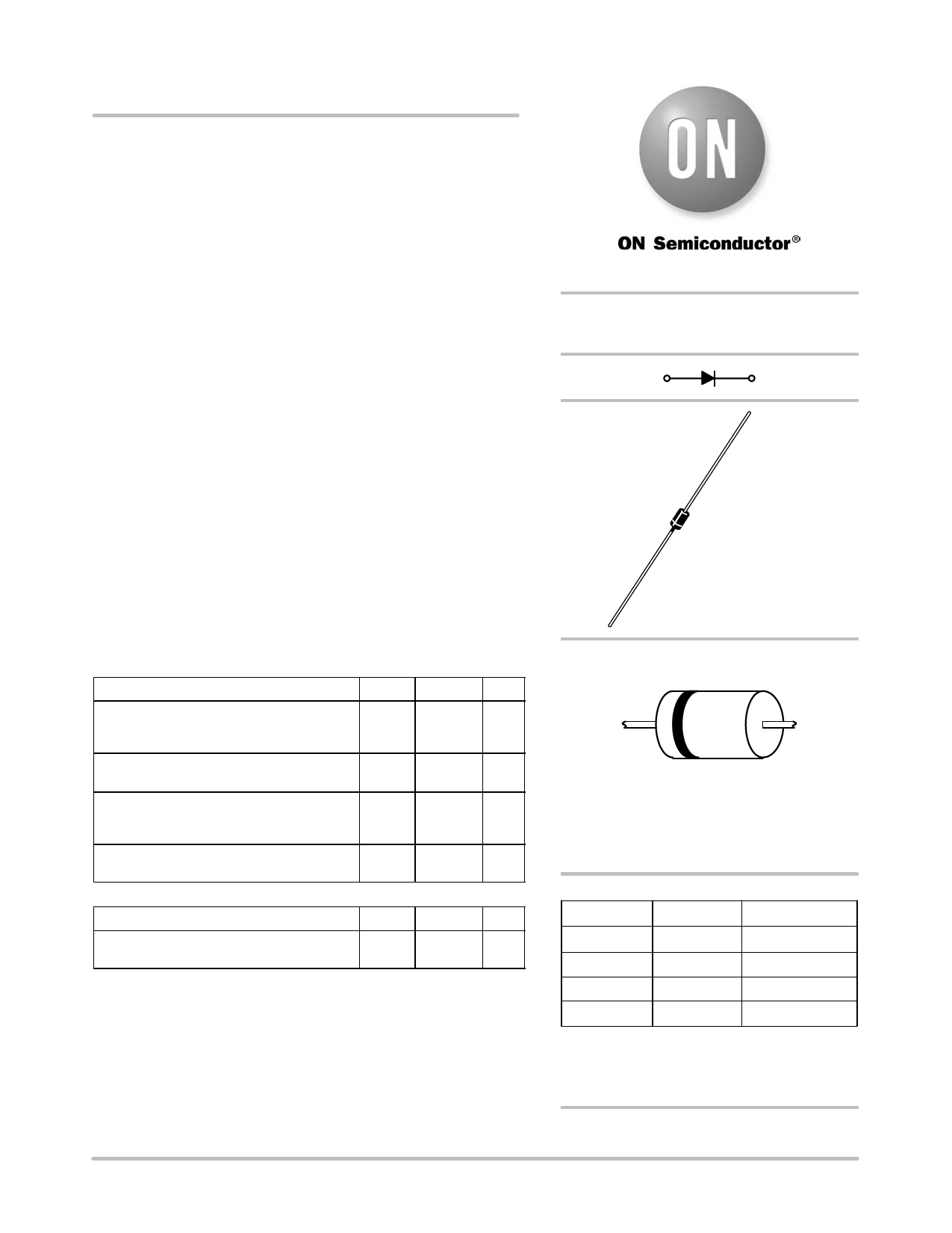
PLASTIC
AXIAL LEAD
CASE 59
MARKING DIAGRAM
A
MUR260
YYWW G
G
A = Assembly Location
Y = Year
WW = Work Week
G = Pb−Free Package
(Note: Microdot may be in either location)
ORDERING INFORMATION
Device
Package
Shipping†
MUR260
Axial Lead** 1000 Units/Bag
MUR260G
Axial Lead** 1000 Units/Bag
MUR260RL Axial Lead** 5000/Tape & Reel
MUR260RLG Axial Lead** 5000/Tape & Reel
†For information on tape and reel specifications,
including part orientation and tape sizes, please
refer to our Tape and Reel Packaging Specifications
Brochure, BRD8011/D.
**This package is inherently Pb−Free.
Preferred devices are recommended choices for future use
and best overall value.
© Semiconductor Components Industries, LLC, 2006
1
July, 2006 − Rev. 4
Publication Order Number:
MUR260/D
Share Link: 