AMIS-30521 데이터 시트보기 (PDF) - ON Semiconductor
부품명
상세내역
제조사
AMIS-30521 Datasheet PDF : 28 Pages
| |||
AMIS−30521, NCV70521
through the inherent parasitic drain−bulk diode of the
transistor.
Depending on the desired current range and the
micro−step position at hand, the RDS(on) of the low−side
transistors will be adapted such that excellent current−sense
accuracy is maintained. The RDS(on) of the high−side
transistors remain unchanged, see also the DC−parameter
table for more details.
PWM Current Control
A PWM comparator compares continuously the actual
winding current with the requested current and feeds back
the information to a digital regulation loop. This loop then
generates a PWM signal, which turns on/off the H−bridge
switches. The switching points of the PWM duty−cycle are
synchronized to the on−chip PWM clock.
The frequency of the PWM controller can be doubled to
reduce the over−all current−ripple with a factor of two.
Icoil
To further reduce the emission, an artificial jitter can be
added to the PWM frequency. (see Table 12, SPI Control
Register 1). The PWM frequency will not vary with changes
in the supply voltage. Also variations in motor−speed or
load−conditions of the motor have no effect. There are no
external components required to adjust the PWM frequency.
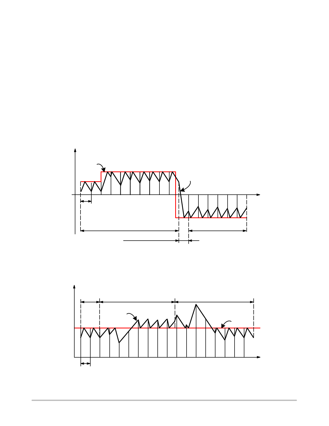
Automatic Forward & Slow−Fast Decay
The PWM generation is in steady−state using a
combination of forward and slow−decay. The absence of
fast−decay in this mode, guarantees the lowest possible
current−ripple “by design”. For transients to lower current
levels, fast−decay is automatically activated to allow
high−speed response. The selection of fast or slow decay is
completely transparent for the user and no additional
parameters are required for operation.
Set value
Actual value
0
t
T PWM
Forward & Slow Decay
Forward & Slow Decay
Fast Decay & Forward
Figure 7. Forward & Slow/Fast Decay PWM
PC20070604.1
Automatic Duty Cycle Adaptation
In case the supply voltage is lower than 2*Bemf, then the
duty cycle of the PWM is adapted automatically to >50% to
maintain the requested average current in the coils. This
process is completely automatic and requires no additional
parameters for operation.
Icoil
Duty Cycle
< 50 %
Duty Cycle > 50 %
Duty Cycle < 50 %
Actual value
Set value
TPWM
Figure 8. Automatic Duty Cycle Adaptation
t
PC20070604.2
http://onsemi.com
11
Share Link: 