NJM3548 데이터 시트보기 (PDF) - Japan Radio Corporation
부품명
상세내역
제조사
NJM3548 Datasheet PDF : 9 Pages
| |||
NJM3548
s FUNCTIONAL DESCRIPTION
The circuit NJM3548 is a high side driver capable of driving resistive or inductive loads not exceeding 2 A.
The driver has an error indicating function which generates an Error output signal when a fault condition has
occurred.
The circuits NJM3548 and NJM3545 are complementary drivers with equivalent functions and similar data.
NJM3548 is a source driver and NJM3545 is a sink driver.
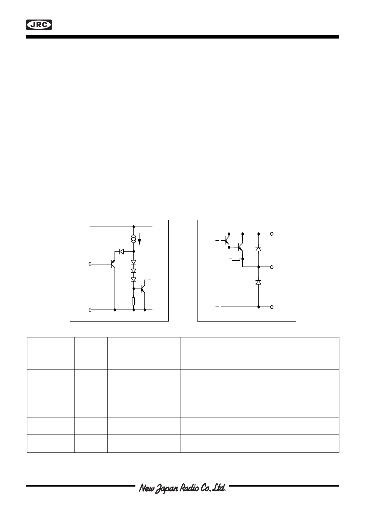
Input stage
The output stage is switched on and off according to the status of the input. LOW level activates the output. If the
input is left open, the circuit will accept it as a HIGH level.
Output stage
The output stage contains a power transistor and two clamping diodes. The diodes are used for terminating line
transients from inductive loads. If the driver is inactive and the output is shorted to VCC the driver will leak a maxi-
mum of 8µA. See figure 18.
Protection circuitry
The circuit contains two protection circuits:
• Overload and Short circuit protection
• Thermal protection
The overload and short circuit protection will be activated at Iout= 3.5 A typically at TJ= +25°C, see figure 20.
The output will be turned off immediately and latched to a high-impedance state after an overload or short circuit
has been detected.
A logic-level change at the input will reset the internal error latch. If the fault still is present at turn-on, the circuit
Supply
I Ref
4
2
Input
Output
5
3
GND
Figure 5. Input stage
Figure 6. Output stage
GND
3
Fault condition
Input
Normal
0
1
VOUT Short to VCC
0
1
VOUT Short to GND 0
1
Open load
0
1
Over temperature 0
T =130
J
°C
1
Figure 7. Error table
LOW
HIGH
LOW
HIGH
LOW
HIGH
LOW
HIGH
LOW
HIGH
Output
1 ON
0 OFF
1 ON
0 OFF
0 OFF
0 OFF
1 ON
0 OFF
0 OFF
0 OFF
Error
LOW=ERROR
HIGH=Normal
How to resume normal operation
1 HIGH
1 HIGH
0 LOW
0 LOW
0 LOW
1 HIGH
0 LOW
1 HIGH
0 LOW
1 HIGH
——
——
Remove fault condition.
Remove fault condition.
Turn off and on after fault condition is removed.
——
Attach proper load to output or turn off the driver.
——
Temperature is reduced to approx 120°C, or turn off the driver.
——
Share Link: 