NJM3771 데이터 시트보기 (PDF) - Japan Radio Corporation
부품명
상세내역
제조사
NJM3771 Datasheet PDF : 9 Pages
| |||
NJM3771
s FUNCTIONAL DESCRIPTION
Each channel of the NJM3771 consists of the following sections: an H-bridge output stage, capable of driving up
to 650 mA continuous motor current (or 500 mA, both channels driven), a logic section that controls the output
transistors, an S-R flip-flop, and two comparators. The oscillator is common to both channels.
Constant current control is achieved by switching the current to the windings. This is done by sensing the (peak)
voltage across a current-sensing resistor, R , effectively connected in series with the motor winding, and feeding
S
that voltage back to a comparator. When the motor current reaches a threshold level, determined by the voltage at
the reference input, VR, the comparator resets the flip-flop, which turns off the output transistors. The current
decreases until the clock oscillator triggers the flip-flop, which turns on the output transistors again, and the cycle is
repeated.
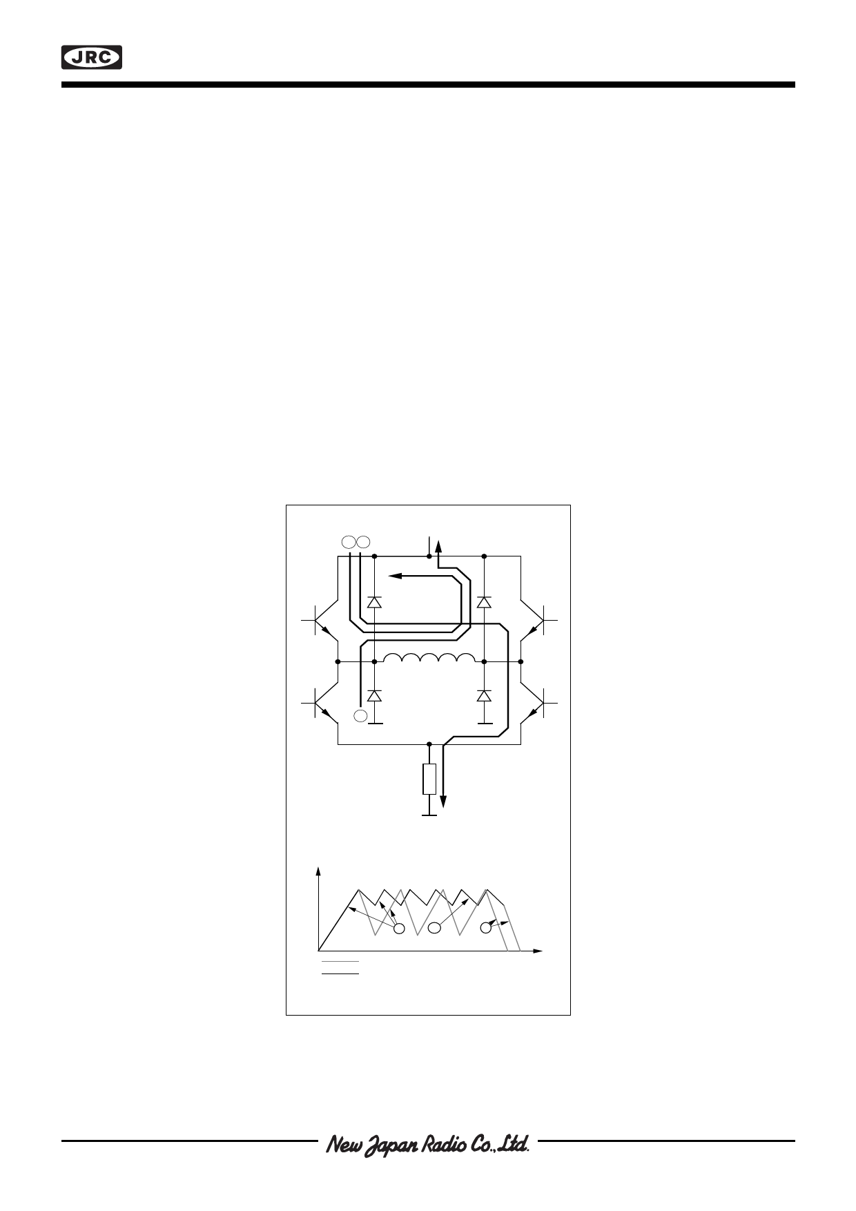
The current-decay rate during the turn-off portion of the switching cycle, can be selected fast or slow by the CD
input.
In slow current-decay mode, only one of the lower transistors in the H-bridge (those closest to the negative
supply) is switched on and off, while one of the upper transistors is held constantly on. During turn-off, the current
recirculates through the upper transistor (which one depends on current direction) and the corresponding free-
wheeling diode connected to VMM, see figure 3.
In fast current decay mode, both the upper and lower transistors are switched. During the off-time, the freewheel-
ing current is opposed by the supply voltage, causing a rapid discharge of energy in the winding.
Fast current decay may be required in half- and microstepping applications when rapid changes of motor current
are necessary. Slow current decay, however, gives less current ripple, and should always be selected, if possible,
to minimize core losses and switching noise.
21
3
Rs
Motor Current
1
2
FAST Current Decay
SLOW Current Decay
3
Time
Figure 3. Output stage with current paths
during turn -on, turn-off and phase shift
Share Link: 