NJM3776D2 데이터 시트보기 (PDF) - Japan Radio Corporation
부품명
상세내역
제조사
NJM3776D2 Datasheet PDF : 9 Pages
| |||
NJM3776
s APPLICATIONS INFORMATION
Output current
The maximum peak output, sink/source, current is 500 mA. But due to the power handling capacity of the package
this current can only be used for a short period of time (1mS). Recommended max continuous output current is 200
mA/output transistor. This is practical when driving MOS FET power transistors, since a high peak output current
capability will rapidly charge/discharge the gate capacitance, while the continuous current usage is very small.
Current control
The regulated output current level to the motor winding is determined by the voltage at the reference input and the
value of the sensing resistor, RS. The peak current through the sensing resistor (and the motor winding) can be
expressed as:
IM,peak = 0.1·VR / RS [A]
With a recommended value of 0.1 ohm for the sense resistor R , a 5 V reference voltage will produce an output
S
current of approximately 5 A. RS should be selected for maximum motor current. Chopping frequency, winding
inductance and supply voltage also affect the current, but to much less extent.
For accurate current regulation, the sensing resistor should be a 0.5 - 1.5 W precision resistor, i. e. less than 1%
tolerance and low temperature coefficient.
Recirculating diodes
Care must be taken to assure that the recirculating current from the motor winding has a free path at all times, when
designing the external H-bridge otherwise may the voltage reach dangerous levels at the outputs. See figure 3.
Make sure that there are recirculating diodes included in the transistors, or if not design in external diodes. Also
make sure that these diodes are sufficient for the application i.e. regarding recovery time, voltage drop etc.
+5 V
Phase 1 Dis1 VR1
10 11 8
NJM3776
VCC 13
V CC
C1 SGND 1
9
7
–
+
RQ
S
Rt
12 kΩ
RC 12
Ct
4700 pF
+
–
SQ
+
R
–
15 14
17
16
Phase 2
Dis 2 VR2
C2
18
SGND 2
Pwr GND 1
1
2 T1BL
4 T1AL
5 T1AU
3 T1BU
6 VBB1
19 V BB2
22 T2BU
20 T2AU
21 T2AL
23 T2BL
24
Pwr GND2
PHASE CH 2
DISABLE CH 2
REFERENCE VOLTAGE CH 2
1000pF
Vmm
R1
270Ω
R2
390Ω
Q1
IRF9Z34
R3
270Ω
R4
390Ω
Q2
IRF9Z34
R5
390Ω
R6
270Ω
R8
1kΩ
Q3
IRFZ34
+
R7
390Ω
R8
270Ω
Q4
IRFZ34
Rs
0.11Ω
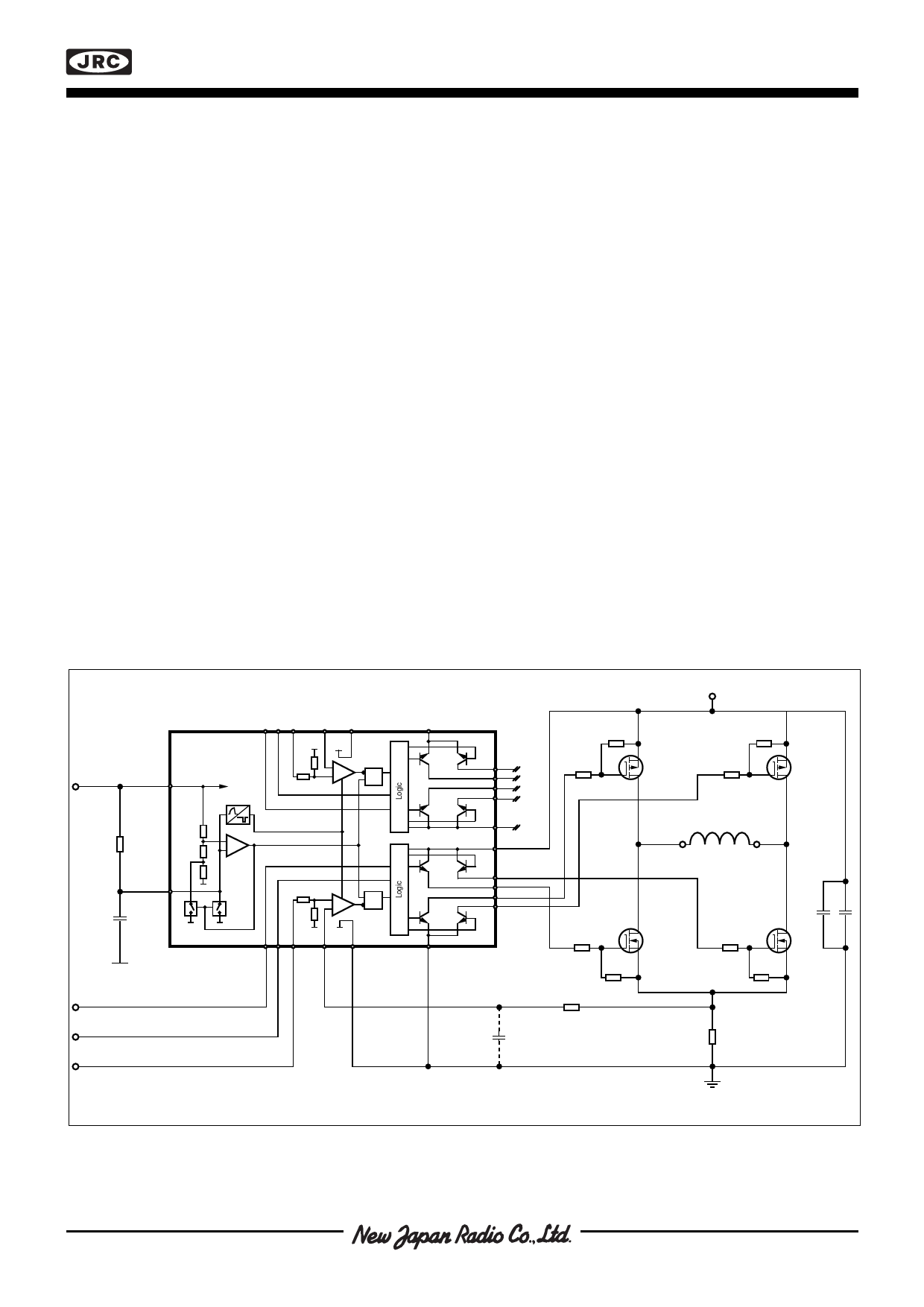
Figure 6. Typical 5A stepper motor driver application with NJM3776. One channel shown.
Share Link: 