NJU9214 데이터 시트보기 (PDF) - Japan Radio Corporation
부품명
상세내역
제조사
NJU9214 Datasheet PDF : 28 Pages
| |||
NJU9214
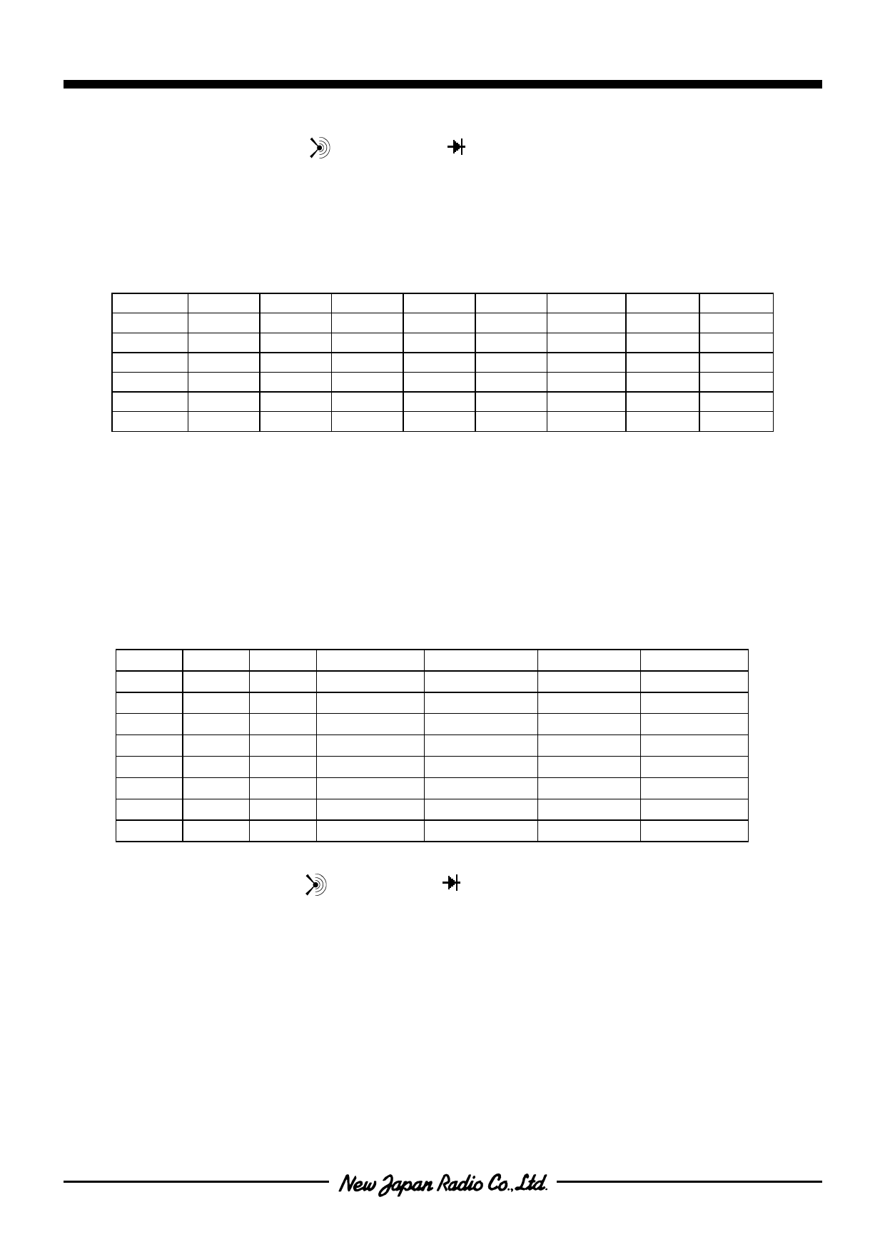
(Note) Frequency measurement and revolution measurement are always set to the Auto-Range.
Ranges of continuity test (
), diode check (
), ADP, DCA and ACA measurement are always
fixed to the default ranges. Just after the power-on operation or mode changing, the range is set to the
default range.
In the ADP measurement, three units are displayed by setting of RC1 to RC3 terminals.
The R1 to R6 of above range control table are set as a range corresponding to below table.
RANGE DCV
ACV DCmA ACmA
R1
400mV 400mV
–
–
R2
∗4V
∗4V ∗40mA ∗40mA
R3
40V
40V 400mA 400mA
R4
400V
400V
–
–
R5
4000V 4000V
–
–
R6
–
–
–
–
(NOTE) The " ∗ " mark means the default range.
Ω
∗400Ω
4kΩ
40kΩ
400kΩ
4000kΩ
40MΩ
f
∗100Hz
1000Hz
10kHz
100kHz
1000kHz
–
rpm
∗6000
60000
600k
–
–
–
C
∗4nF
40nF
400nF
4uF
40uF
400uF
Changing to DC400mA range or AC400mA is available by only manual operation. Auto-range operation cannot
change to these ranges.
( 2 - 1 - 3 ) Range setting ( Lock type switch & Manual-range : KMS = " H ", RMS = " L " )
The range setting shown in below table is available with RC1 to RC3 terminal
RC1
RC2
RC3
DCV, ACV DCmA, ACmA
Ω
H
H
H
400mV
4mA
400Ω
L
H
H
4V
40mA
4kΩ
H
L
H
40V
400mA
40kΩ
L
L
H
400V
4000mA
400kΩ
H
H
L
4000V
4mA
4000kΩ
L
H
L
400mV
4mA
40MΩ
H
L
L
400mV
4mA
400Ω
L
L
L
400mV
4mA
400Ω
( NOTE ) Frequency and revolution measurements are always set to the Auto-range.
C
4nF
40nF
400nF
4uF
40uF
400uF
4nF
4nF
Ranges of continuity test (
), diode check (
), ADP, DCA and ACA measurement are always fixed
to the default ranges
Share Link: 