NVD0.1CKK-M6 데이터 시트보기 (PDF) - Power-One Inc.
부품명
상세내역
제조사
NVD0.1CKK-M6 Datasheet PDF : 11 Pages
| |||
NV Series: 4 - 6W DC/DC Converters
9-36V, 18-36V, 36-72V & 16-75V Inputs
3.3V, 5.0V, 12V, 15V, ±5.0V, ±12V, ±15V & ±24V Outputs
Product Specifications
Oct 2001
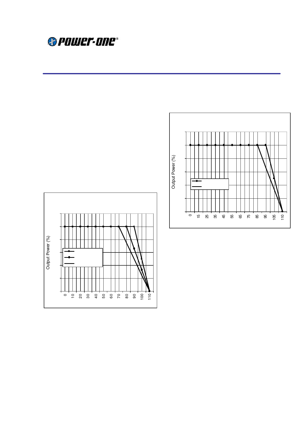
Temperature Derating Curves
The derating curves below give an indication of
the output power achievable with and without
forced air-cooling. However in the final application
the temperature rise of the converter is also
influenced by factors such as heat conduction
through the leads to the PCB, orientation, the
temperature of surrounding components and the
input voltage. To ensure the reliability of the
converter, care must be taken to guarantee that
the maximum case temperature is not exceeded
under any conditions. The measurement point for
case temperature is specified on the mechanical
drawing (Tc).
Temperature derating for 18-36V and 36-75V
input voltage ranges :
Output Power Vs Ambient Temp. & Airflow
120
100
80
60
400LFM (2 m/s)
200LFM (1 m/s)
40
0 LFM
20
0
Ambient Temp. (deg °C)
The 9-36V and 18-75V input voltage versions of
this series feature a 4:1 input voltage range and
can achieve operation at full power at 85ºC
ambient temperature with only convection cooling.
Temperature derating for 9-36V and 18-75V input
voltage ranges :
Output Power Vs Ambient Temp. & Airflow
120
100
80
60
200LFM (1 m/s)
40
0 LFM
20
0
Ambient Temp. (deg °C)
Typical Application
This series of converters does not require any
external components for proper operation.
However, if the distribution of the input voltage to
the converter contains significant inductance, a
capacitor across the input terminals may be
required to stabilize the input voltage. A minimum
of 0.47µF, quality electrolytic / ceramic capacitor
is recommended for this purpose. For output
decoupling it is recommended to connect, directly
across the output pins, a 0.47µF ceramic
capacitor (for 3.3V and 5V outputs) or a 0.27µF
ceramic capacitor (for other outputs).
Care must be taken to ensure the maximum rated
output capacitance for the device is not exceed
when dimensioning decoupling capacitors in the
system as this could cause the unit to detect an
overload and enter a ‘hiccup’ mode of operation.
18-Oct-01
Rev 1.0
www.power-one.com
Page 5 of 11
Share Link: 