PT2308P-C 데이터 시트보기 (PDF) - Princeton Technology
부품명
상세내역
제조사
PT2308P-C Datasheet PDF : 12 Pages
| |||
Tel: 886-2-66296288
Fax: 886-2-29174598
URL: http://www.princeton.com.tw
2-Channel 300mW Class AB Power Amplifier
PT2308P
4. Output Coupling Capacitor Co
Single power single-ended (SE) configuration generates a DC bias at the output of the amplifier; a
coupling capacitor must be placed at the output to block the DC bias from being sent to the load and
connect a RL at the signal output terminal. The low cut-off frequency may be needs to adjust to
correspond to different load (speaker or earphone) specifications. Similar to the input coupling
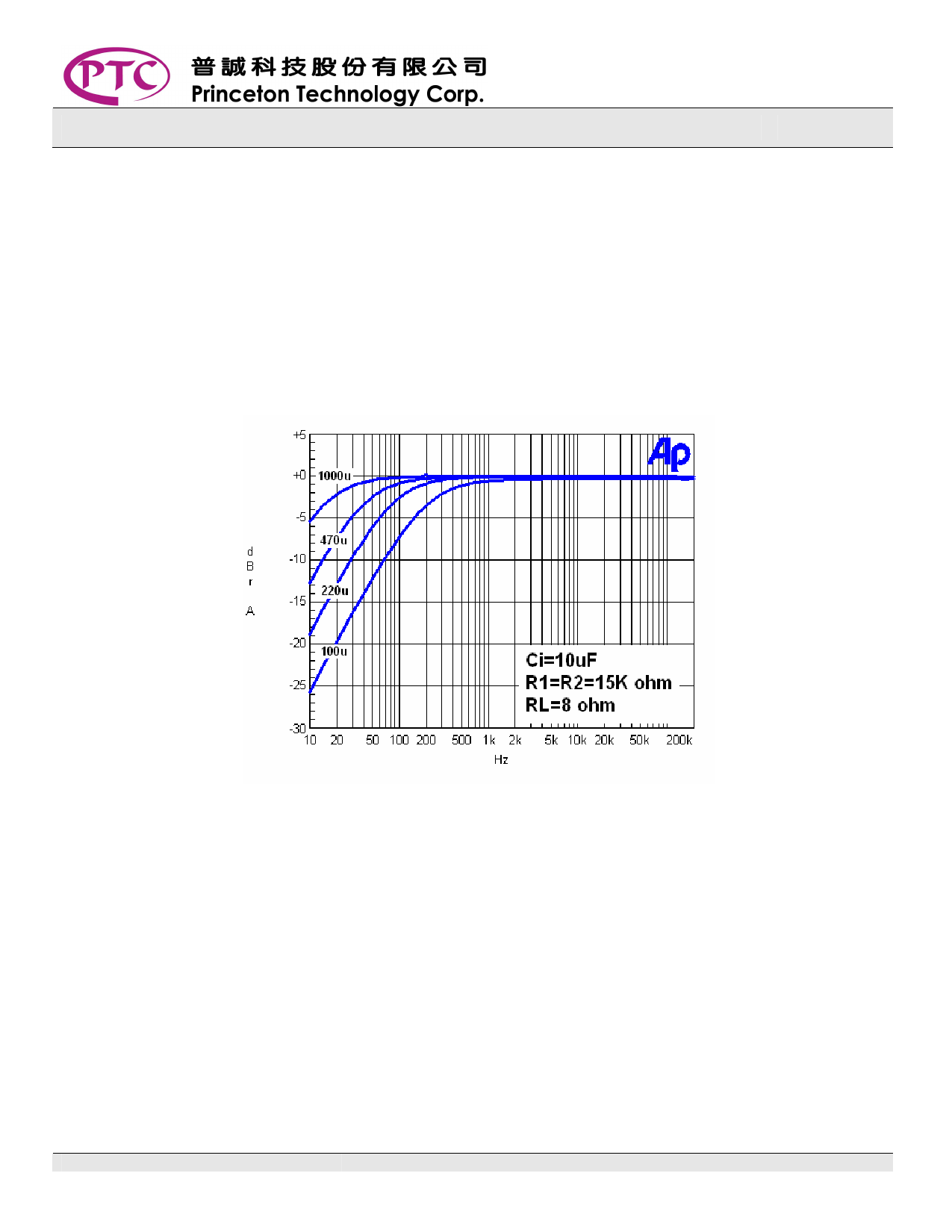
capacitor, the output coupling capacitor and impedance of the load form a 1st order high-pass filter,
the low cut-off frequency is determined by the equation:
fc(highpass)=1/2πRLCo
The diagram below shows the frequency response when: Co=1000µF/470µF/220µF/100µF.
5. Discharging Resistor (R3)
When the PT2308 is powered ON, the output coupling capacitor Co will start charging. When there is
no load connected at Vout, there will be a DC voltage present. At this time, if a load is suddenly
connected (usually earphone or speaker for general applications), the charged Co will then
discharge through Vout to the load, causing a very loud popping sound, thus, it is recommended to
connect a R3 to regulate the discharge of Co.
The time it takes to discharge is T=CoR3.
The recommended resistance value for R3 is between 1KΩ ~ 10KΩ, to prevent loading effect from the
amplifier. If the load (ex. Speaker) is permanently connected then R3 can be neglected.
PT2308P V1.0
-6-
November, 2005
Share Link: 