RSP-1500 데이터 시트보기 (PDF) - Astrodyne Corporation
부품명
상세내역
제조사
RSP-1500 Datasheet PDF : 4 Pages
| |||
1500W�Single�Output�Power�Supply
1500W Single Output Power Supply
RRSsPp--11550000 sseerriieess
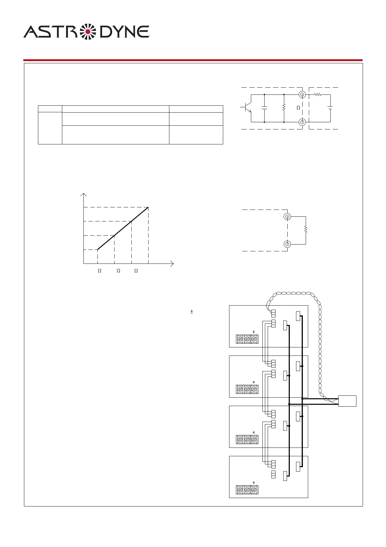
2.Alarm�Signal�Output
(1)Alarm�signal�is�sent�out�through�"P OK"�&�"P OK�GND"�pins
(2)An�external�voltage�source�is�required�for�this�function. The�maximum�applied�voltage
is�50V�and�the�maximum�sink�current�is�10mA
(3)Table�2.1�explain�the�alarm�function�built-in�the�power�supply
Function
Description
Output�of�alarm(P OK)
P OK
The�signal�is�"Low"�when�the�power�supply�is above
65%�of�the�rated�output�voltage-Power�OK
The�signal�turns�to�be�"High"�when�the�power�supply
is�under�65%�of�the�rated�output�voltage-Power�Fail
Low
(0.5V�max�at�10mA)
High�or�open
(External�applied�voltage
10mA max.)
Table�2.1�Explanation�of�alarm
P OK
0.1uF 100K
R
V
P OK�GND
External�voltage�and�R
(The�max.�Sink�is�10mA and�50V)
Fig.�2.2�Internal�circuit�of�P OK�(Open�collector�method)
3.Output�Voltage�TRIM
(1)Adjustment�of�output�voltage�is�possible�between�70~100%(Typ.)�of�the�rated�output�which�is�shown�in�Fig.�3.1
(2)Connecting�a�resistor�externally�between TRIM�and-S�on�CN1�or�CN2�that�is�shown�in�Fig.�3.2.
Vout
100%
90%
80%
70%
R
0
470 1.8K OPEN
Fig.�3.1�External�Resistor�(Typical)
TRIM
CN1
or
CN2 -S
R(0.5W)
Fig.�3.2�Output�voltage�trimming
4.Current�Sharing
(1)Parallel�operation�is�available�by�connecting�the�units�shown�as�below
(+S,-S�and�LS�are�connected�mutually�in�parallel):
(2)The�voltage�difference�among�each�output�should�be�minimized�that�less�than 2%�is�required
(3)The�total�output�current�must�not�exceed�the�value�determined�by�the�following�equation
(Output�current�at�parallel�operation)=(The�rated�current�per�unit)�x�(Number�of�unit)�x�0.9
(4)�In�parallel�operation�4�units�is�the�maximum,�please�consult�the�manufacture�for�other
applications
(5)�When�remote�sensing�is�used�in�parallel�operation,�the�sensing�wire�must�be�connected�only
to�the�master�unit
No.1(Master)
AC/L AC/N
No.2(Slave)
AC/L AC/N
V+
+S
-S CN1
LS
V-
+S
-S CN2
LS
V+
+S
-S CN1
LS
V-
+S
-S CN2
LS
No.3(Slave)
AC/L AC/N
V+
+S
-S CN1
LS
V-
+S
-S CN2
LS
+S +V
Load
-V
-S
No.4(Slave)
AC/L AC/N
V+
+S
-S CN1
LS
V-
+S
-S CN2
LS
WWW.ASTRODYNE.COM
300 Myles StandishFiBle�lNvadme.,:RTSaP-u1n50t0o-SnP,ECM���A200052-078-8106
Ph: 1-800-823-8082
Fax: 508-823-8181
Share Link: 