TDA1908 데이터 시트보기 (PDF) - STMicroelectronics
부품명
상세내역
제조사
TDA1908 Datasheet PDF : 12 Pages
| |||
TDA1908
THERMAL SHUT-DOWN
The presence of a thermal limiting circuit offers the
following advantages:
1) An overload on the output (even if it is perma-
nent), or an abovelimit ambienttemperature can
be easily supported since the Tj cannot be
higher than 150°C.
2) The heatsink can have a smaller factor of safety
compared with that of a conventional circuit.
There is no possibility of device damage due to
high junction temperature.
If, for any reason, the junction temperature in-
crease up to 150°C, the thermal shut-down sim-
ply reduces the power dissipation and the
current consumption.
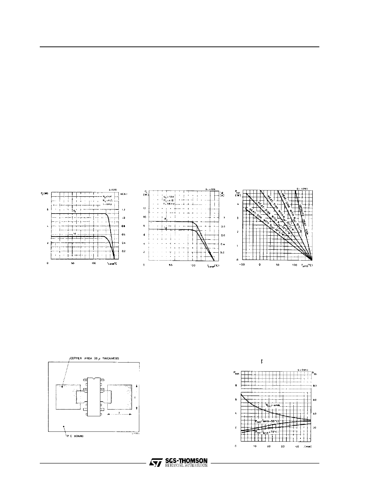
The maximum allowable power dissipation de-
pends upon the size of the external heatsink (i.e. its
thermal resistance); fig. 25 shows the dissipable
power as a function of ambient temperature for
different thermal resistance.
Figure 24. Output power
and drain current vs.
case temperature
Figure 25. Output power
and drain current vs.
case temperature
Figure 26. Maximum
power dissipation vs.
ambient temperature
MOUNTING INSTRUCTIONS
The thermal power dissipated in the circuit may be
removed by soldering the tabs to a copper area on
the PC board (see Fig. 27).
During soldering, tab temperature must not exceed
260°C and the soldering time must not be longer
than 12 seconds.
Figure 27. Mounding example
Figure 28. Maximum
power dissipation and
thermal resistance vs.
side ” ”
10/12
Share Link: 