MRFIC2006 데이터 시트보기 (PDF) - Motorola => Freescale
부품명
상세내역
제조사
MRFIC2006 Datasheet PDF : 8 Pages
| |||
RECOMMENDED OPERATING RANGES
Parameter
Symbol
Value
Unit
Supply Voltage Ranges
Bias Voltage Range
RF Frequency Range
VCC1, VCC2
Vbias
f
1.8 to 4.0
0 to 5.0
500 to 1000
Vdc
Vdc
MHz
ELECTRICAL CHARACTERISTICS (VCC1, VCC2, Vbias = 3.0 V, TA = 25°C, f = 900 MHz, Zo = 50 Ω unless otherwise noted)
Characteristics (1)
Min
Typ
Max
Unit
Supply Current — Total
ICC1
ICC2
I Bias
—
46
55
mA
—
14
—
mA
—
29
—
mA
—
3.0
—
mA
Small Signal Gain
19
23
26
dB
Input Return Loss, RF IN Port
—
15
—
dB
Output Return Loss, RF OUT Port
—
15
—
dB
Reverse Isolation
—
35
—
dB
Output Power at 1.0 dB Gain Compression
+12
+15.5
—
dBm
3rd Order Intercept Point (Out)
—
+ 25
—
dBm
5th Order Intercept Point (Out)
—
+ 21
—
dBm
NOTE:
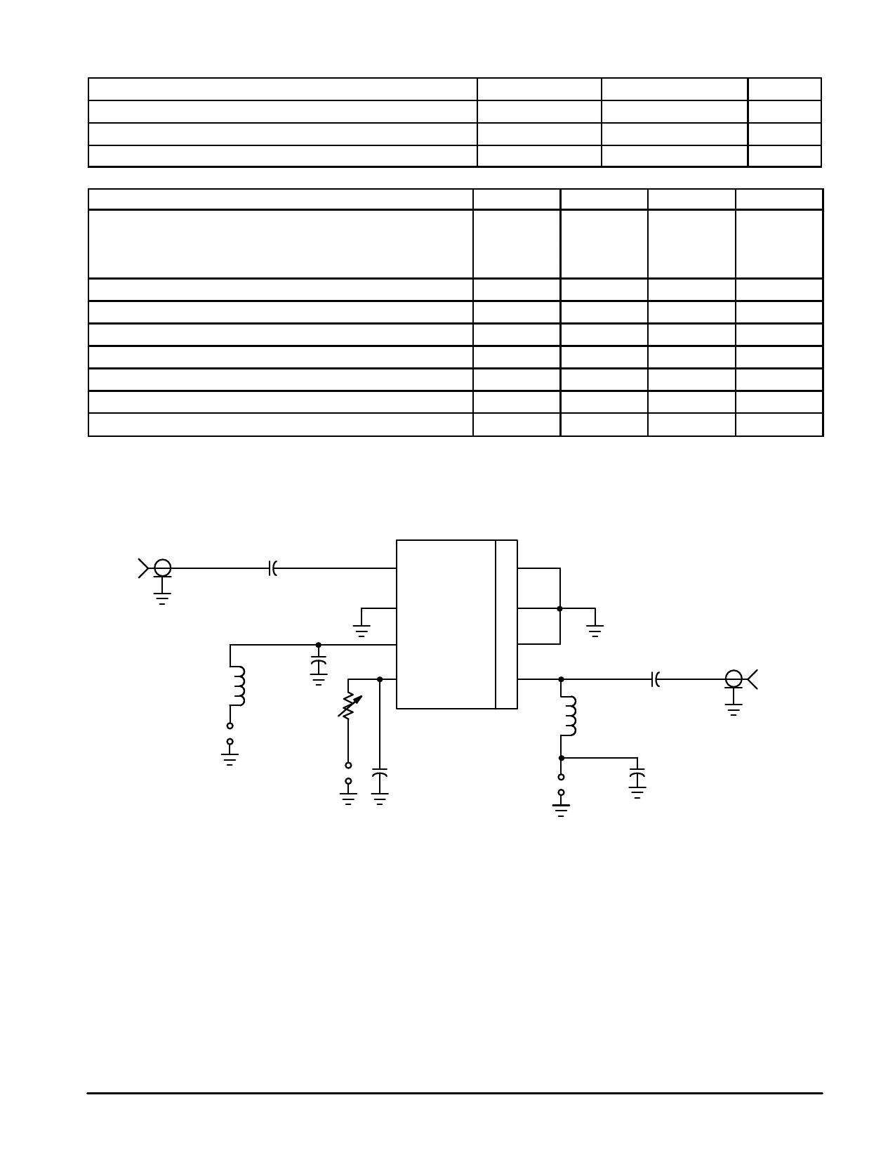
1. All electrical characteristics measured in test circuit schematic shown in Figure 1 below.
RF IN
50 Ω
C1
L1
VCC1 +
–
C3
R1
Vbias +
–
5
4
6
3
DUT
7
2
8
1
C2
L2
C4
VCC2 +
C5
–
RF OUT
50 Ω
C1, C2 — 100 pF Chip Capacitor
C3, C5 — 1.0 nF Chip Capacitor
C4 — 10 nF Chip Capacitor
L1 — 150 nH Chip Inductor
L2 — 10 nH Chip Inductor
R1 — Resistor Optional
RF Connectors — SMA Type
Board Material — Epoxy/Glass εr = 4.5,
Dielectric Thickness = 0.014″ (0.36 mm)
Figure 1. Typical Biasing Configuration
MRFIC2006
2
MOTOROLA RF DEVICE DATA
Share Link: 