HMP9701A 데이터 시트보기 (PDF) - Intersil
부품명
상세내역
제조사
HMP9701A Datasheet PDF : 20 Pages
| |||
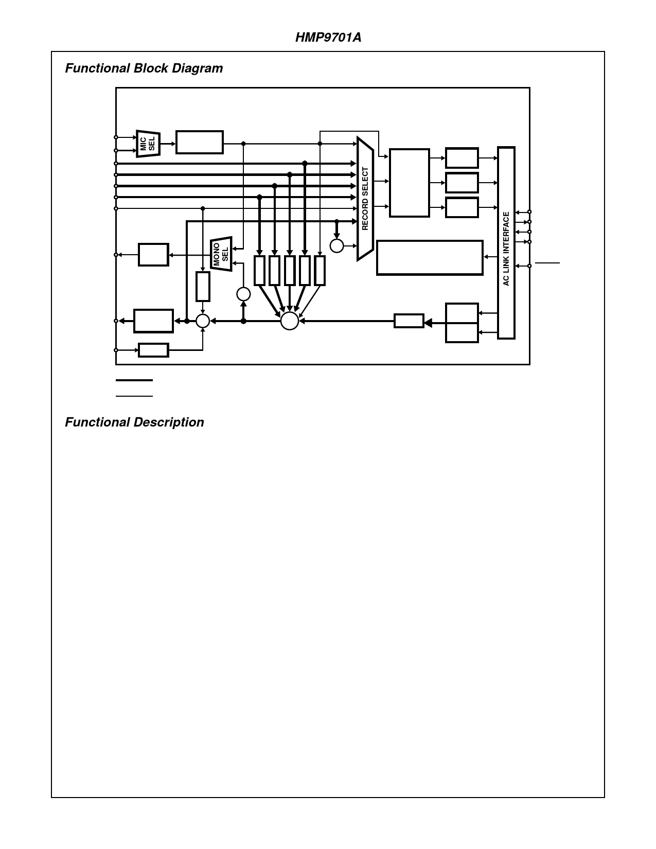
Functional Block Diagram
HMP9701A
HMP9701A AC’97 AUDIO CODEC
MIC1
MIC2
LINE_IN
CD
VIDEO
AUX
PHONE
GAIN
0dB / 20dB
MONO_OUT
MONO
VOL
G
A
M
LINE_OUT
MASTER
VOL
∑
PC_BEEP
GAM
∑
GGGGG
AAAAA
MMMMM
∑
∑
RECORD
GAIN
Σ∆ A/D
Σ∆ A/D
Σ∆ A/D
AC’97
CONTROL/CONFIGURATION
(64 REGISTERS)
GAM
Σ∆ D/A
Σ∆ D/A
SYNC
BIT_CLK
SDATA_OUT
SDATA_IN
RESET
STEREO SIGNAL PATH
MONO SIGNAL PATH
Functional Description
The HMP9701A is a full-duplex stereo audio codec compliant
to the AC’97 Codec specification. This component is designed
for use in multimedia and business personal computers. The
codec includes full duplex stereo converters, a mic pass
through ADC, complete on-chip anti-alias filtering, and a 5
channel analog mixer with programmable gain and attenuation.
Analog Inputs
The HMP9701A has 4 stereo inputs (LINE_IN, CD, VIDEO,
and AUX), two microphone level inputs (MIC1 and MIC2), and
one mono line level input (PHONE). A multiplexer is provided
to independently select the right and left record sources from
the analog inputs listed above. In addition, the output stereo
mix (LINE_OUT) or its mono equivalent may also be selected
as a record source. A gain block is available to amplify the
MIC inputs by 20dB to compensate for the difference between
line levels and typical condenser microphone levels.
Besides being fed to the Record Select Mux, all analog
inputs can be mixed (see Analog Mixer) with the stereo out-
put from the Playback DACs. Note: all analog inputs except
PHONE and PC_BEEP can be output on MONO_OUT.
There is a dedicated analog input, PC_BEEP, for the
standard “Beep” signal provided on most PC/Compatible
computers for power on self test and boot audio status
indication. This input is mixed into each channel of the
stereo line outputs.
Record ADCs
The HMP9701A provides 3 Σ∆ ADCs to record one dedi-
cated microphone input and 2 user selectable analog inputs.
The user selectable analog inputs are routed to the stereo
ADCs via an programmable Input Multiplexer. The multi-
plexer is programmed to select the 2 record channels via the
Record Select register (1Ah).
Each of the record channels pass through a programmable
gain block before each ADC. The record gain for each chan-
nel is set individually and ranges from 0dB to 22.5dB in
1.5dB increments (see Record Gain Registers 1Ch and
1Eh). The gain block can also be used to mute each chan-
nel. Note: an additional gain block provides 20dB of gain on
the MIC channel if activated (see MIC Volume register 0Eh).
The HMP9701A uses oversampling Σ∆ ADCs which only
require a single pole passive filter for anti-alias filtering. The
filter for the left, right and MIC channels is realized by placing
a 1nF capacitor between the AFILT1, AFILT2, and AFILT3
pins and analog ground respectively.
Playback DACs
The HMP9701A uses oversampling single bit Σ∆ DACs to
convert the stereo playback sample to an analog line level
output. The output of the DACs pass through internal recon-
struction filters that do not require any external components.
2
Share Link: 