HER3006 데이터 시트보기 (PDF) - Formosa Technology
부품명
상세내역
제조사
HER3006 Datasheet PDF : 2 Pages
| |||
HER3001 THRU HER3006
30.0 AMP HIGH EFFICIENCY RECTIFIERS
FEATURES
* Low forward voltage drop
* High current capability
* High reliability
* High surge current capability
* High speed switching
MECHANICAL DATA
* Case: Molded plastic
* Epoxy: UL 94V-0 rate flame retardant
* Lead: Lead solderable per MIL-STD-202,
method 208 guranteed
* Polarity: As Marked
* Mounting position: Any
* Weight: 5.60 grams
VOLTAGE RANGE
50 to 600 Volts
CURRENT
30.0 Amperes
.120(3.05) DIA.
.115(2.92)
.180(4.53)
.170(4.32)
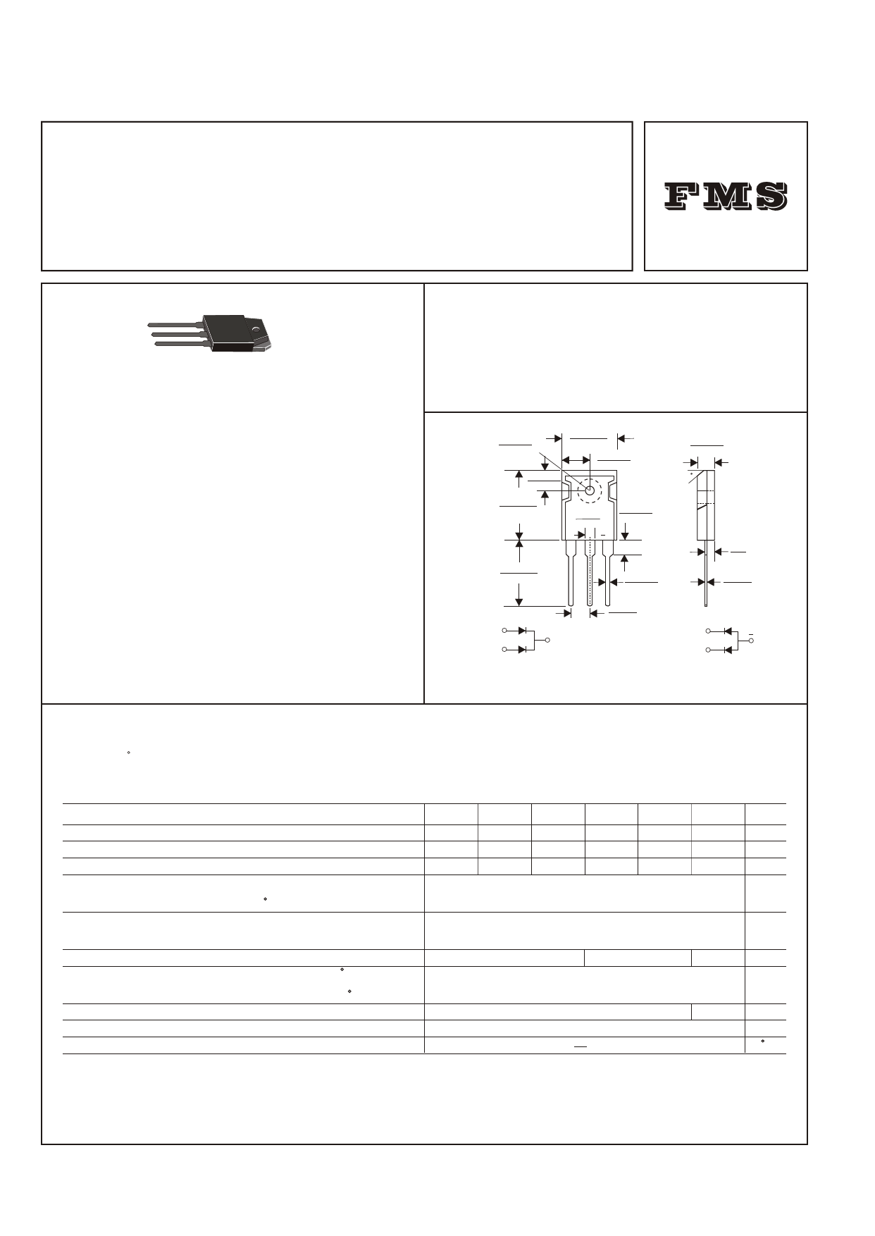
TO-247
.635(16.13)
.625(15.88)
.320(8.13)
.310(7.87)
.840(21.34)
.820(20.83)
.12(3.0)
.11(2.8)
.170(4.32)
.150(3.81)
.205(5.21)
.195(4.49)
30
.800(20.32)
.770(19.56)
.050(1.27)
.045(1.14)
.095
(2.4)
.030(0.8)
.020(0.5)
.225(5.7)
.205(5.2)
PIN 1
+
PIN 1
PIN 3
CASE
PIN 2
Positive CT
Suffix "C"
PIN 3
CASE
PIN 2
Negative CT
Suffix "A"
Dimensions in inches and (millimeters)
MAXIMUM RATINGS AND ELECTRICAL CHARACTERISTICS
Rating 25 C ambient temperature uniess otherwies specified.
Single phase half wave, 60Hz, resistive or inductive load.
For capacitive load, derate current by 20%.
TYPE NUMBER
Maximum Recurrent Peak Reverse Voltage
Maximum RMS Voltage
Maximum DC Blocking Voltage
Maximum Average Forward Rectified Current
.375"(9.5mm) Lead Length at Tc=75 C
Peak Forward Surge Current, 8.3 ms single half sine-wave
superimposed on rated load (JEDEC method)
Maximum Instantaneous Forward Voltage at 15.0A
Maximum DC Reverse Current
Tc=25 C
at Rated DC Blocking Voltage
Tc=100 C
Maximum Reverse Recovery Time (Note 1)
Typical Junction Capacitance (Note 2)
Operating and Storage Temperature Range TJ, TSTG
HER3001 HER3002 HER3003 HER3004 HER3005 HER3006 UNITS
50
100 200
300
400
600
V
35
70 140
210
280
420
V
50
100 200
300
400
600
V
30.0
A
300
1.0
1.3
10.0
200
60
125
-65 +150
A
1.85
V
mA
mA
100 nS
pF
C
NOTES:
1. Reverse Recovery Time test condition: IF=0.5A, IR=1.0A, IRR=0.25A
2. Measured at 1MHz and applied reverse voltage of 4.0V D.C.
Share Link: 