LA1135M 데이터 시트보기 (PDF) - SANYO -> Panasonic
부품명
상세내역
제조사
LA1135M Datasheet PDF : 18 Pages
| |||
LA1135, 1135M
Proper cares in using IC
1. Bias condition: RF VCC % IF VCC
2. Avoid coupling between the antenna tuning circuit and the local oscillation.
3. Connect detection capacitor C15 across pins 13 (output) and 14 (VCC) so that no leakage of the IF signal to the GND line
occurs. (If connected to GND, the tweet and the usable sensitivity may get worse.) Radiation from C15 may cause harmonics
in the IF signal to return to the RF stage, thereby leading to more tweet interference. So, connect C15 as close to pins 13, 14
as possible. Consider the direction of the capacitor and separate it from the ANT circuit.
4. For R9, use a semifixed resistor with VSM considered.
5. When designing the coils, consider the following conditions.
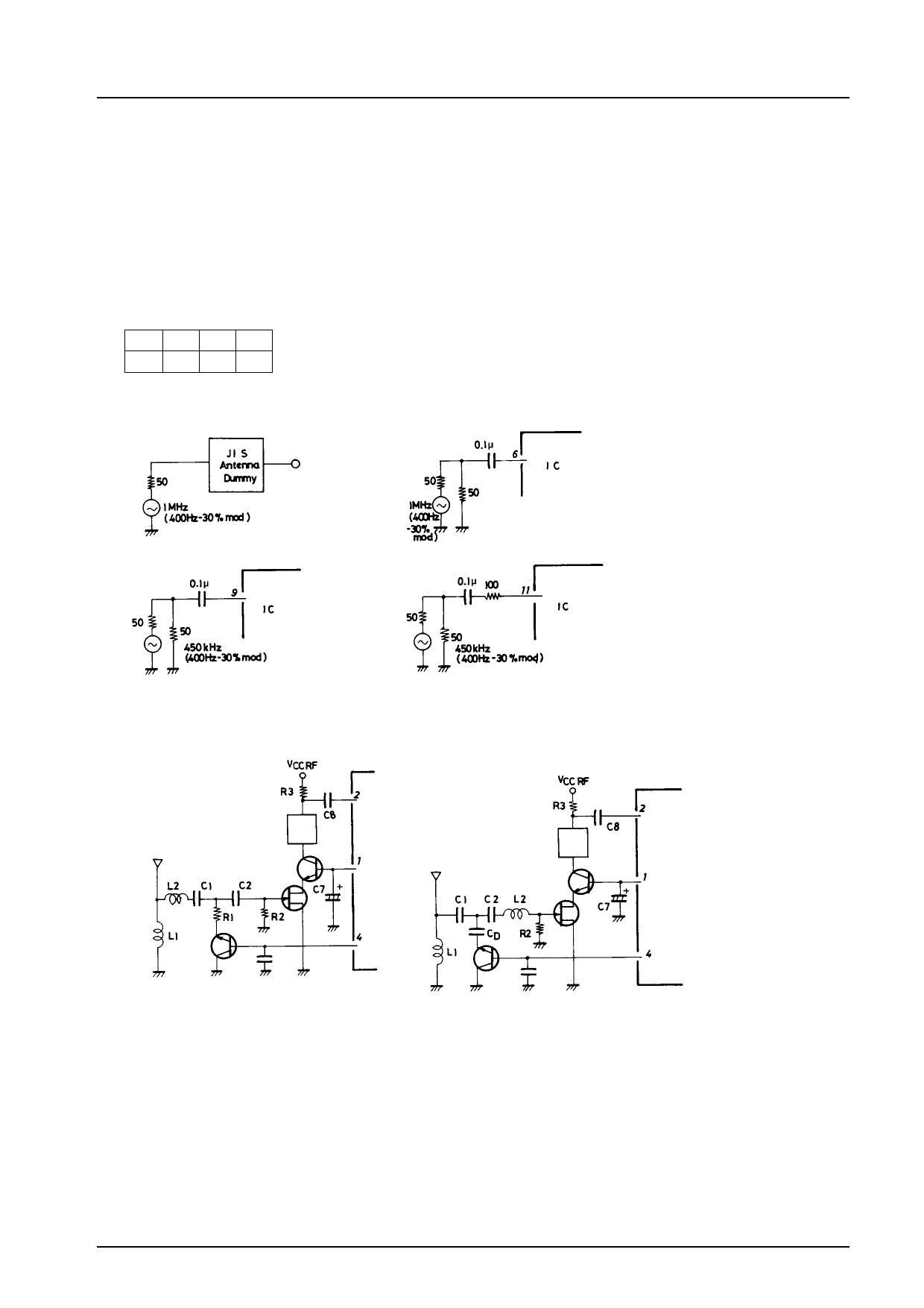
Shown below is the input level at each pin at which the detection output at fm = 400 Hz 30% mod becomes –25 dB.
ANT MIX IF Det
16.0 28.0 45.0 61.0 (dBµ)
How to apply input to each stage
ANT stage
ANT input
MIX stage
IF stage
Det stage
Unit (resistance: Ω, capacitance: F)
6. ANT damping
To make the ANT damping constant within the receiving band, change the application circuit as shown below.
Old circuit
New circuit
Double tuning
Double tuning
Measures
Replace R1 with CD.
CD (2000 pF to 3000 pF or thereabouts)
Relocate L2.
Damping (600 kHz to 1400 kHz) Old circuit –15 dB
New circuit –4 dB
No. 1272-6/18
Share Link: 