TSP160C 데이터 시트보기 (PDF) - PANJIT INTERNATIONAL
부품명
상세내역
제조사
TSP160C Datasheet PDF : 7 Pages
| |||
TSP058C - TSP320C
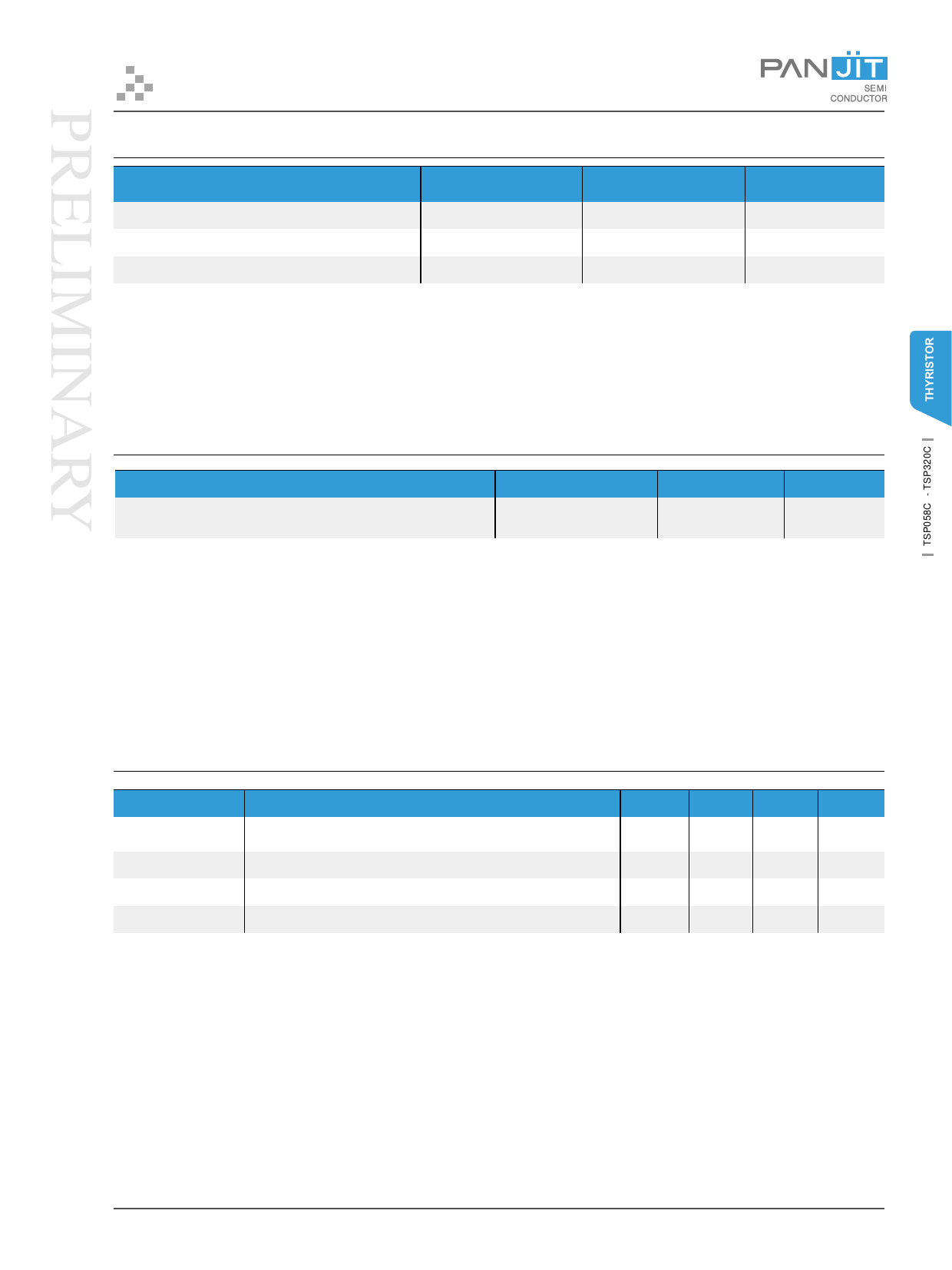
MAXIMUM THERMAL RATINGS
Rating
Symbol
Value
Unit
Storage Junction Temperature Range
Operating Junction Temperature Range
Operating Ambient Temperature Range
Notes:
PCB board mounted on minimum foot print.
TSTG
TJ
Ta
-50 to 150
OC
-40 to 150
OC
-40 to 65
OC
THERMAL CHARACTERISTICS
Characteristic
Thermal Resistance Junction to Leads TL on tab adjacent to
plastic. Both leads soldered to identical pad sizes.
Symbol
RθJL
Value
Max. 20
Unit
OC / W
Notes:
The junction to lead thermal resistance represents a minimum limiting value with both leads soldered to a large near-infinite heatsink. The
junction to ambient thermal resistance depends strongly on board mounting conditions and typically is 3 to 6 times higher than the junction
to lead resistance. The data shown is to be used as guideline values for preliminary engineering.
ELECTRICAL CHARACTERISTICS (TC = 25°C UNLESS OTHERWISE NOTED)
Parameters
Repetitive Peak
Off-State Current
Breakover Current
Holding Current1
On-State Voltage
Test Conditions
Symbol
VD = rated VDRM
I DRM
f = 60 Hz, ISC = 1 Arms, Vac = 1 KVrms, RL = 1 KΩ , 1/2 AC cycle I BO
10/1000µs waveform, ISC = 10A, VOC = 62 V, RL = 400 Ω
IH
I T = 1 A, Tw = 300 µs, 1 pulse
VT
Min.
150
Max.
5
800
5
Unit
µA
mA
mA
V
Notes:
Specific IH values are available by request.
Ver: June 2001
PAGE 3
Share Link: 