SX1223 데이터 시트보기 (PDF) - Semtech Corporation
부품명
상세내역
제조사
SX1223 Datasheet PDF : 25 Pages
| |||
SX1223
frequencies corresponding to the transmission of the two possible values ‘0’ and ‘1’; these frequencies are then
separated by twice the specified single sided frequency deviation ∆f.
4.1.2 Crystal Oscillator
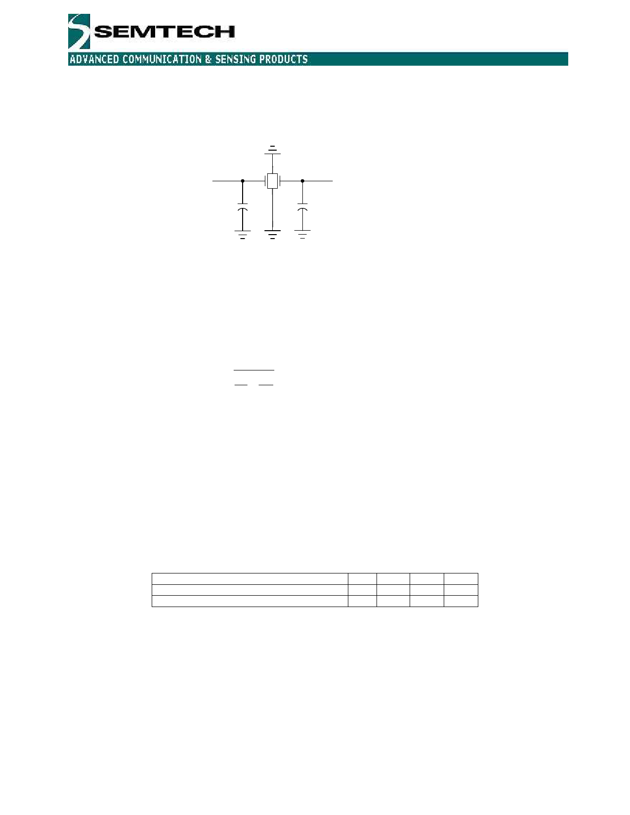
The crystal oscillator (XCO) provides the PLL with the reference signal. The schematic of the crystal oscillator's
external components for 16 MHz is shown in Figure 2.
XTB, pin 7
5p6
XTA, pin 8
5p6
Figure 2: External crystal oscillator circuit with additional (optional) external capacitances
The crystal should be connected between pins XTA and XTB (pin 8 and 7). Either internal or external loading
capacitors for the crystal can be used. Internal capacitors can be enabled by setting the XCOcap_en bit to 1. Faster
start-up time is expected when using external capacitors. The total capacitance when XCOcap_en=1 (and no
external capacitors) is 9 pF. Using a crystal with a load capacitance of 9 pF will give the expected oscillation
frequency.
If XCOcap_en=0, the loading capacitors can be calculated by the following formula:
CL =
1
1
+
1
+ C parasitic
C1 C2
The parasitic capacitance is the pin input capacitance and PCB stray capacitance. For instance, for a 9pF load
crystal and a total parasitic capacitance of 6 pF the recommended values of the external load capacitors are 5.6 pF.
If an external reference is going to be used instead of a crystal, the signal shall be applied to pin 7, XTB. Due to
internal biasing, AC coupling is recommended for use between the external reference and the XTB pin.
The start-up time of the crystal oscillator can vary from 150us to 800us depending on the settings shown in Table
15. Therefore, to save current consumption, the XCO should be turned on before any other circuit block. During
start-up the XCO amplitude will eventually reach a sufficient level to trigger the M-counter. After counting 2 M-
counter output pulses the rest of the circuit is enabled.
Two bits are available to speed up the crystal oscillator start-up: XCO_high_I increases the bias current and
XCO_quick_start boosts this current but only at the start; the first output pulse from the M-divider turns this boost
current off. Typical values for XCO start-up time and current consumption are tablulated below:
XCO_quick_start, XCO_high_I
IDDST [uA]
TS_OS [us]
00 01 10 11
200 250 900 950
800 750 200 150
Table 1: Oscillator start-up time
A reference clock can be generated by SX1223 for use by an external microcontroller. The ClkOut_en configuration
bit determines the status of the CLKOUT pin. When set high CLKOUT is enabled, otherwise it’s disabled. When
enabled, the output frequency at CLKOUT is the crystal oscillator frequency divided by 16, and is then 1 MHz for a
crystal at 16 MHz. This clock signal is disabled in Sleep Mode. When disabled, the CLKOUT pin is set to ground.
4.1.3 VCO
The VCO is fully integrated and has no external components. It oscillates at 1.8 GHz and is divided by 2 or 4 in the
900 MHz or the 450 MHz band respectively (FreqBand = 1 or 0). Additionally two bits in the configuration registers
set the VCO frequency and three bits control the bias current. The two VCO_freq bits have to be programmed by
© Semtech 2007
www.semtech.com
8
Share Link: 