SX1223 데이터 시트보기 (PDF) - Semtech Corporation
부품명
상세내역
제조사
SX1223 Datasheet PDF : 25 Pages
| |||
SX1223
the user according to the selected frequency band, whereas the three VCO_IB bits can be either forced by the user
or set automatically by the circuit which will select the combination having the best phase noise. This automatic
setting can be enabled by setting the three VCO_IB bits to ‘0’.
Table 2 lists the bias setting used for the different VCO_freq settings in automatic mode. When any of the VCO_IB
bit is set to 1, it will overrule the automatic setting.
RF frequency
425/850 MHz
434/868 MHz
457/915 MHz
475/950 MHz
VCO_IB2
1
1
0
0
VCO_IB1
1
0
1
0
VCO_IB0 VCO_freq1 VCO_freq0
1
0
0
1
0
1
1
1
0
0
1
1
Table 2: VCO bit settings.
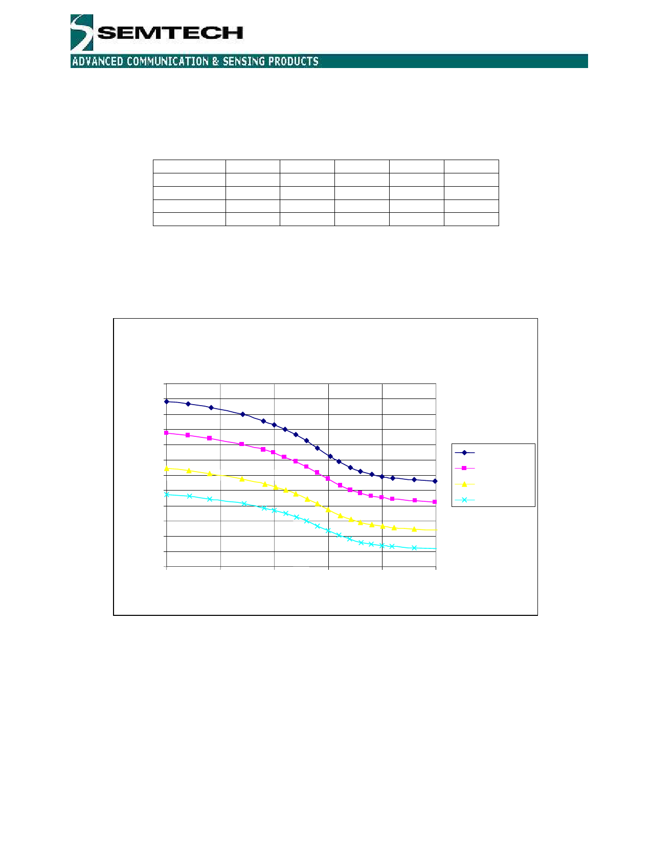
The bias bits optimize the phase noise, and the frequency bits control a capacitor bank in the VCO. The tuning
range, the RF frequency versus varactor voltage, is dependent on the VCO frequency setting, and is shown in
Figure 3. When the tuning voltage is in the range from 1 to 1.6V, the VCO gain is at its maximum, approximately 65-
70 MHz/V. It is then recommended that the varactor voltage is kept as much as possible in this range.
Freq [MHz]
1040
1020
1000
980
960
940
920
900
880
860
840
820
800
0
VCO gain
Vdd=3.3V, LDO_en=1, VCO_IB=0
0.5
1
1.5
2
2.5
Vvaractor [V]
VCO_freq=11
VCO_freq=10
VCO_freq=01
VCO_freq=00
Figure 3: RF frequency vs. varactor voltage and VCO frequency bit
The input capacitance at the varactor pin must be taken into considerations when designing the PLL loop filter. This
can be critical when designing a loop filter with high bandwidth, which gives relatively small component values. The
input capacitance is approximately 6 pF.
For test purposes, the VCO can be bypassed by applying a differential local oscillator (LO) signal to the device on
pin CPOUT and VARIN. A resistor of 18 kΩ to ground and a series capacitor of 47 pF are needed on both pins for
proper biasing. The register bit VCO_by must be set to ‘1’.
© Semtech 2007
www.semtech.com
9
Share Link: 