TA7291J 데이터 시트보기 (PDF) - Toshiba
부품명
상세내역
제조사
TA7291J Datasheet PDF : 14 Pages
| |||
Notes
TA7291AP/AS(J)/AF
· Power On/Off
At power on, VCC must be applied simultaneously or before VS. At power off, VCC must be removed
simultaneously or after VS.
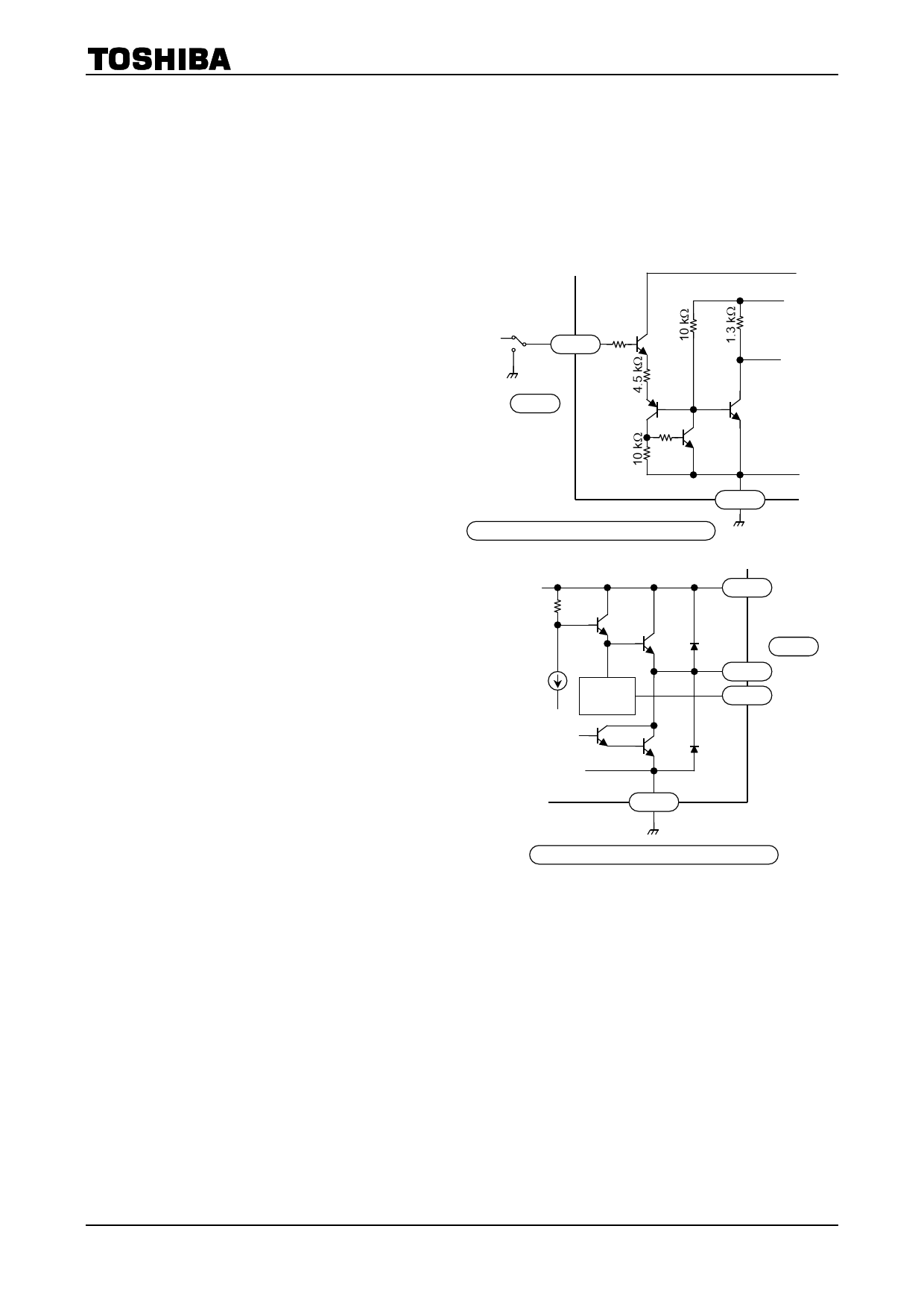
· Input Circuit
VCC standby
A logic high on the VIN pin activates the input
circuit as shown in the figure.
When a voltage greater than or equal to VIN (high)
is applied to the pin, the circuit is active. When a VIN
voltage less than or equal to VIN (low) is applied to
VIN
1 kW
5/9/7
the pin or the pin is grounded, the circuit is
inactive.
When the pin is high, the input current IIN flows
or
6/1/9
into the input circuit. So, be careful about the
5 kW
output impedance of the first stage.
The input hysteresis is 0.7 V (typ.). At power on
(VCC), set both input pins IN1 and IN2 to low.
1/5/1
TA7291AP/TA7291AS (J)/TA7291AF
· Output Circuit
Output high voltage
· Operation based on the Vref voltage
The Vref voltage is increased by twice the value
of VBE (small signal) in the Vref circuit. Then,
the voltage is applied to the base A of Q2 (power
transistor 2). As a result, the voltage which is
reduced by the value of VBE (Q2) appears on the
VOUT pin.
VOUT = Vref + 2VBE-VBE (Q2) ~- Vref + 0.7 V
· Vref pin
The Vref pin must not be left open when unused.
In this case, connect it via a protection resistor
(3 kW or more) to the VS pin. Otherwise, it
might cause oscillation.
Vref must be £ VS.
Q1
Q2
A
Vref
circuit
8/6/15
or 10/3/13
2/7/4 VOUT
4/8/5 Vref
1/5/1
TA7291AP/TA7291AS (J)/TA7291AF
Protection Features
Overcurrent Protection Circuit
The overcurrent protection circuit detects a current flowing through the upper power transistor. If the
current exceeds a predetermined value (about 2.5 A), the circuit turns all the power transistors off.
However, it does not always prevent overcurrent. If an output pin is shorted or grounded, the IC might be
destroyed before operation of the overcurrent protection circuit. So, be sure to connect a resistor or fuse to
the power supply (VS) line. (See “Application Circuit.”)
Thermal Shutdown Circuit
If the chip temperature exceeds a predetermined limit (about 170°C), the thermal shutdown circuit turns
all the power transistors off.
9
2003-02-14
Share Link: 