TDA3605Q 데이터 시트보기 (PDF) - Philips Electronics
부품명
상세내역
제조사
TDA3605Q Datasheet PDF : 16 Pages
| |||
Philips Semiconductors
Multiple voltage regulator with switch
Preliminary specification
TDA3605Q
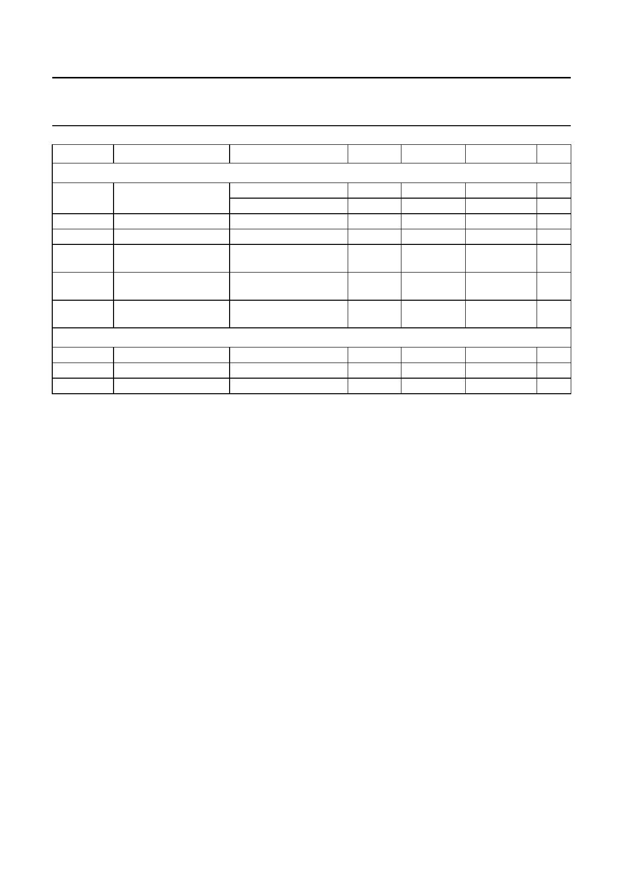
SYMBOL
PARAMETER
CONDITIONS
MIN.
TYP.
MAX.
UNIT
Power switch
Vswd
drop-out voltage
Isw = 1 A; note 10
−
0.45
0.7
V
Isw = 1.8 A; note 10
−
1.0
1.8
V
Isw(dc)
continuous current
VP = 16 V; VSW = 13.5 V 1.8
2.0
−
A
Vswcl
clamping voltage
VP ≥ 17 V
13.5
15.0
16.0
V
IswM
peak current
VP = 17 V;
3
−
−
A
notes 11 and 12
Vswfb
fly back voltage
Isw = −100 mA
−
VP + 3
22
V
behaviour
Isw(sc)
short-circuit current
VP = 14.4 V; Vsw ≤ 1.2 V; −
0.8
−
A
note 12
Back-up switch
Ibu(DC)
continuous current
0.3
0.35
−
A
Vbucl
clamping voltage
VP ≥ 16.7 V
−
−
16
V
Vr
reverse current
VP = 0 V; Vbu = 12.4 V −
−
900
ms
Notes
1. Minimum operating voltage, only if VP has exceeded 6.5 V.
2. The quiescent current is measured in the standby mode. So, the enable inputs of regulators 1 and 3 and the switch
are grounded and R2 = ∞ (see Fig.6).
3. The voltage of the regulator sinks as a result of a VP drop.
4. The rise and fall times are measured with a 10 kΩ pull-up resistor and a 50 pF load capacitor.
5. The delay time depends on the value of the capacitor:
td = -I-Cc---h- × VC (th) = C × ( 750×103) (ms)
6. The drop-out voltage of regulators 1, 2 and 3 is measured between VP and VREGn.
7. At current limit, IREGmn is held constant (see Fig.4 for behaviour of IREGmn).
8. The foldback current protection limits the dissipated power at short-circuit (see Fig.4).
9. The peak current of 300 mA can only be applied for short periods (t < 100 ms).
10. The drop-out voltage of the power switch is measured between VP and Vsw.
11. The maximum output current of the switch is limited to 1.8 A when the supply voltage exceeds 18 V.
A test-mode is built-in. The delay time of the switch will be disabled when a voltage of VP + 1 V is applied to the switch
enable input.
12. At short circuit, Isw(sc) of the power switch is held constant to a lower value than the continuous current after a delay
of at least 10 ms. A test-mode is built-in. The delay time of the switch will be disabled when a voltage of VP + 1 V is
applied to the switch enable input.
1997 Jul 09
10
Share Link: 