TEA1541 데이터 시트보기 (PDF) - Philips Electronics
부품명
상세내역
제조사
TEA1541 Datasheet PDF : 19 Pages
| |||
Philips Semiconductors
SMPS control IC with
synchronization function
Product specification
TEA1541
6.3 Primary current regulation
The IC uses current mode control for its good line
regulation behaviour. The primary current is sensed
indirectly via the voltage at pin DEM.
The ‘on-time’ of the external MOSFET is controlled by the
voltage on pin CTRL which is compared with the internal
simulated primary current information. For pin CTRL
voltages (VCTRL) between 1 and 1.6 V, the on-time is
calculated by the equation:
ton
=
αP
C
S
×
1----.--6----I–--D---VE----MC----T---R---L-
[ ns
]
where:
• ton: the on-time
• αPCS: an internal constant which is approximately 0.9.
• VCTRL: the voltage on pin CTRL
• IDEM: the current drawn from pin DEM during the primary
cycle.
handbook, halfpaf ge
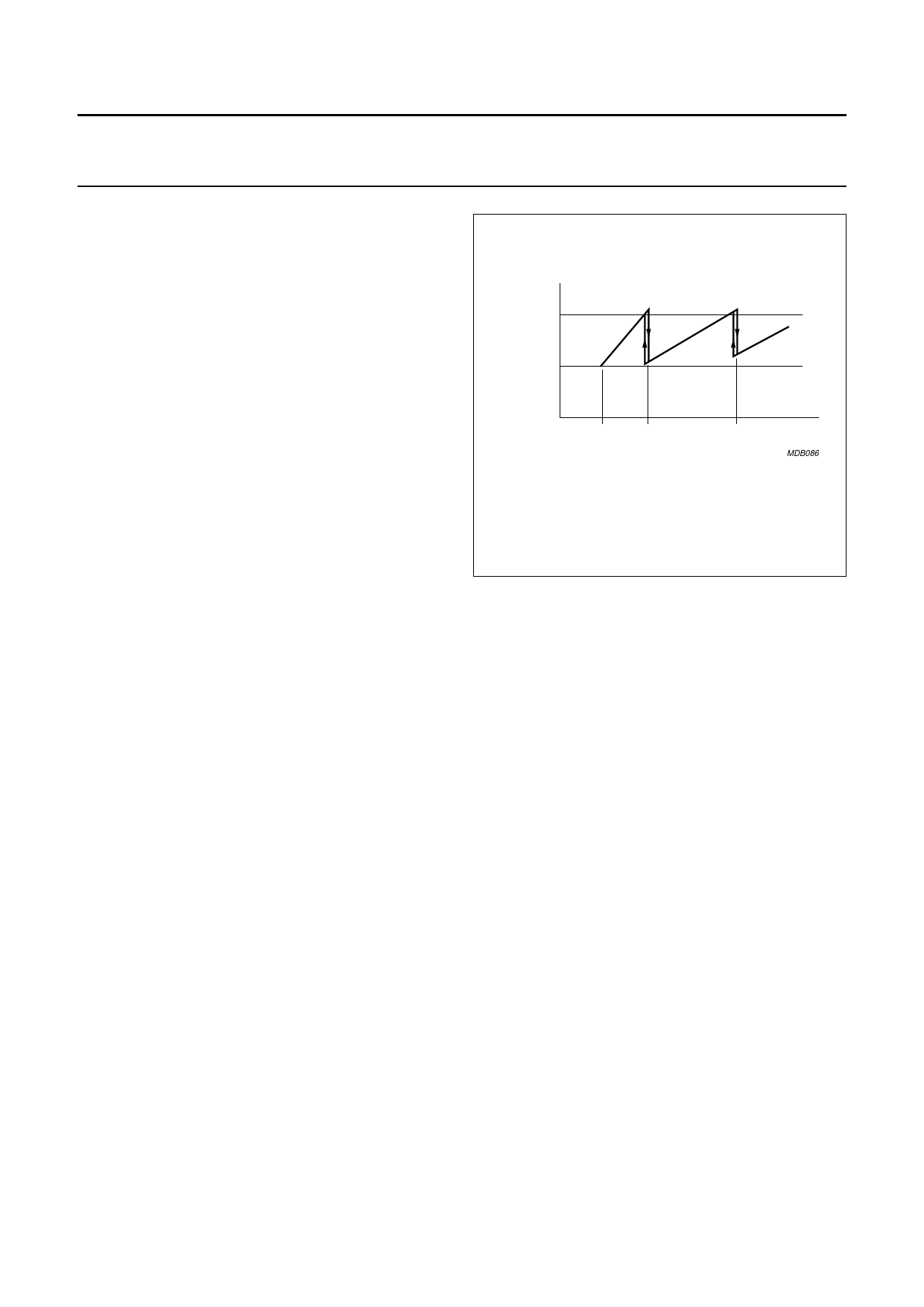
(kHz)
fsmps(max)
fosc
fsync fsync
(min) (max)
2 × fsync
(max)
f
(kHz)
MDB086
Fig.6 Switching frequency as a function of the
synchronizing frequency.
6.4 Oscillator
In synchronized mode, the switching frequency of the
SMPS fsmps is controlled by the synchronizing pulses fsync
at pin CTRL. Synchronized mode prevents noise
disturbance on the CRT monitor screen. Synchronizing
pulses whose frequency is outside of the fosc and fsmps(max)
window of 26 to 54 kHz are divided by an internal
frequency divider. A small frequency hysteresis exists to
ensure a stable frequency switch-over. In unsynchronized
mode, the system runs at fosc (26 kHz). In unsynchronized
mode, at very low power (standby) levels, the frequency of
the VCO and consequently the SMPS switching frequency
is reduced linearly to its low value of approximately 6 kHz
(see Figs 4 and 6).
6.5 Demagnetization
The system always operates in discontinuous conduction
mode to ensure demagnetization of the output transformer
core. A primary cycle only starts when the secondary cycle
has ended.
Pin DEM protects against an output short-circuit on a
cycle-by-cycle basis, by immediately lowering the
switching frequency to give a longer off-time and a lower
operating power.
Demagnetization detection is suppressed automatically at
the start of each secondary cycle for a period tsuppr.
Suppression of demagnetization detection is necessary for
applications where the transformer has a large leakage
inductance, at low output voltages and at start-up.
If, due to a fault condition, pin DEM is left open circuit,
operation of the flyback converter supply immediately
stops, and restarts when the fault situation is removed and
pin DEM is reconnected.
If, during start-up, a fault condition causes pin DEM to be
shorted to ground, operation of the flyback converter
supply stops after the first cycle, and the IC then begins a
restart cycle. This situation continues until the short-circuit
is removed. Short-circuit protection is also active at full
power to ensure limitation of peak current.
2003 Aug 11
8
Share Link: 