TEA2029 데이터 시트보기 (PDF) - STMicroelectronics
부품명
상세내역
제조사
TEA2029 Datasheet PDF : 47 Pages
| |||
TEA2028 - TEA2029 APPLICATION NOTE
V - FUNCTIONAL DESCRIPTION
Majority of the on-chip analog functions were com-
puter simulated and results such as temperature
variation, technological characteristic dispersion
and stability, have led to the enhancement and
implementation of actually employed structures. A
parallel in-depth study of the device implemented
in form of integrated sub-sections is provided to
analyze the overall performance in a TV set.
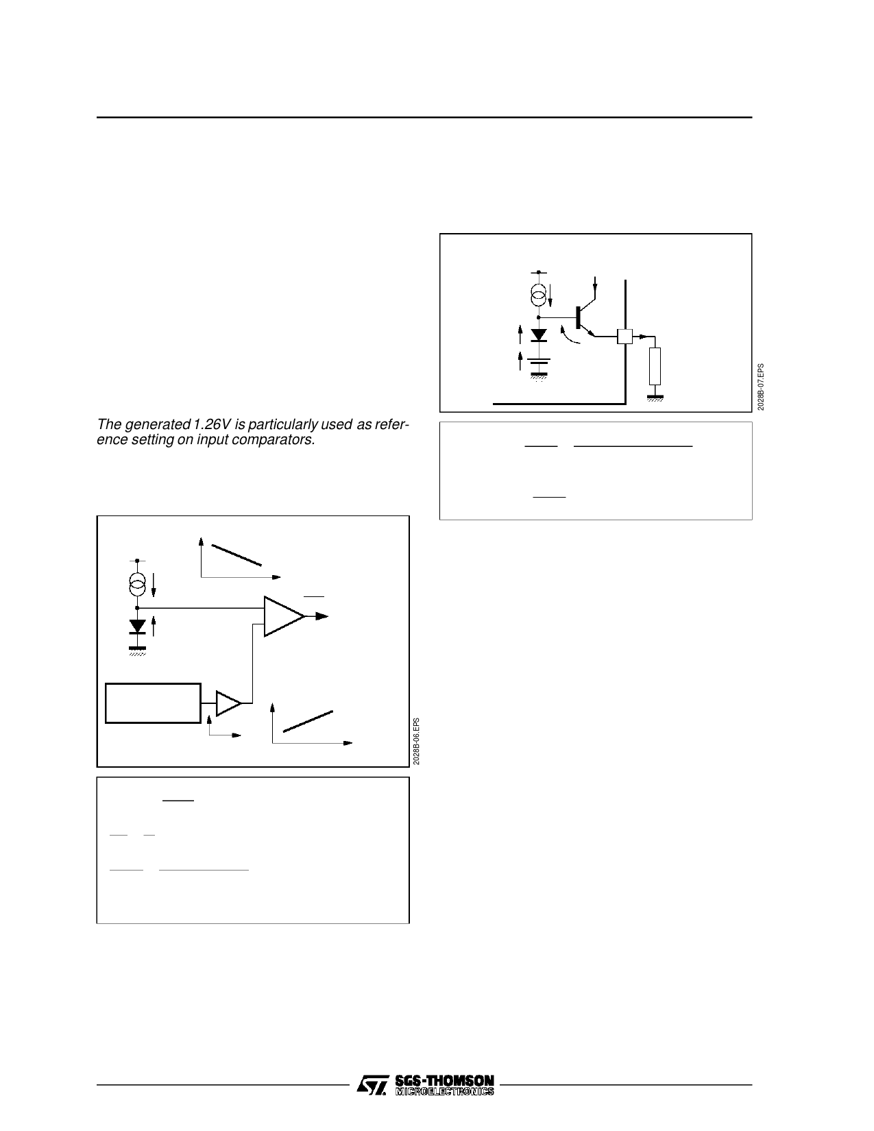
V.1 - Internal Voltage and Current References
V.1.1 - 1.26V Voltage reference
For optimum operation of the device, an accurate
and temperature-stable voltage generator inde-
pendent from VCC variations is used (Band-gap
type generator).
The generated 1.26V is particularly used as refer-
ence setting on input comparators.
V.1.1.1 - Generator block diagram
Figure 3
VBE
I
VBE
-2mV/°C
T
dVO
dt
=
0
Σ
VO = VBE + A . λ
= 1.26V
λ
GENERATOR
A
λ +0.086mV/°C
T
with
λ
=
K⋅
q
T
=
25.7mV
at
+
25oC
dλ
dT
=
K
q
=
+
0.086mV/oC
dVBE
dT
=
VBE(25’) −
T
1.26
=
-
2mV/oC
if Aλ = 1.26 - VBE
Then : VO = 1.26V (temperature-independant)
In practice, maximum drift due to temperature can
be + 0.23mV/oC
i.e., ± 1.5% for a ∆T of 80oC.
V.1.2 - Current reference
This is implemented using the 1.26V generator in
combination with an external resistor.
Figure 4
+
VCC
IREF
VBE1
1.26V
Band
Gap
VBE2
I14
14
R EXT
3.32kΩ
1%
IREF
≈
I14
=
V14
REXT
=
1.26
+
VBE1 −
REXY
VBE2
Let’s I14 = I and VEB1 = VBE2
then
:
IREF
=
1.26
REXT
=
380µA
Thus, it follows that IREF is accurate and inde-
pendent of both VCC and temperature.
A set of current generators proportional to IREF
current are used in various circuit blocks.
V.2 - Line Sync. Extraction
Horizontal and vertical time bases should be syn-
chronized with corresponding sync. pulses trans-
mitted inside the infra-black portion of video signal.
The duty of this stage is to extract these sync
pulses. The output signal, called composite sync,
contains the vertical sync which is transmitted by
simple inversion of line sync. pulses.
The vertical sync pulse is then extracted from this
composite signal.
The main advantage of this arrangement is its
ability to operate at video input signal levels falling
within 0.2V to 3V peak-to-peak range and at any
average value.
The operating principle is to lock the black level of
the input signal (Pin 27) onto internaly fixed voltage
(VN) and then memorize the average voltage of the
sync pulse by using an integrating capacitor con-
nected to Pin 26.
Finally, the composite sync signal is delivered by a
comparator the inputs of which are driven by V50%
and video signals.
6/46
Share Link: 