TJA1041 데이터 시트보기 (PDF) - Philips Electronics
부품명
상세내역
제조사
TJA1041 Datasheet PDF : 24 Pages
| |||
Philips Semiconductors
High speed CAN transceiver
Product specification
TJA1041
Pins RXD and ERR will reflect any wake-up requests
(provided that VI/O is present).
GO-TO-SLEEP COMMAND MODE
The go-to-sleep command mode is the controlled route for
entering sleep mode. In go-to-sleep command mode the
transceiver behaves as if in standby mode, plus a
go-to-sleep command is issued to the transceiver. After
remaining in go-to-sleep command mode for the minimum
hold time (th(min)), the transceiver will enter sleep mode.
The transceiver will not enter the sleep mode if the state of
pins STB or EN is changed or the UVBAT, pwon or
wake-up flag is set before th(min) has expired.
SLEEP MODE
The sleep mode is the second-level power saving mode of
the transceiver. Sleep mode is entered via the go-to-sleep
command mode, and also when the undervoltage
detection time on either VCC or VI/O elapses before that
voltage level has recovered. In sleep mode the transceiver
still behaves as described for standby mode, but now
pin INH is set floating. Voltage regulators controlled by
pin INH will be switched off, and the current into pin VBAT
is reduced to a minimum. Waking up a node from sleep
mode is possible via the wake-up flag and (as long as the
UVNOM flag is not set) via pin STB.
Internal flags
The TJA1041 makes use of seven internal flags for its
fail-safe fallback mode control and system diagnosis
support. Table 1 shows the relation between flags and
operating modes of the transceiver. Five of the internal
flags can be made available to the controller via pin ERR.
Table 2 shows the details on how to access these flags.
The following sections describe the seven internal flags.
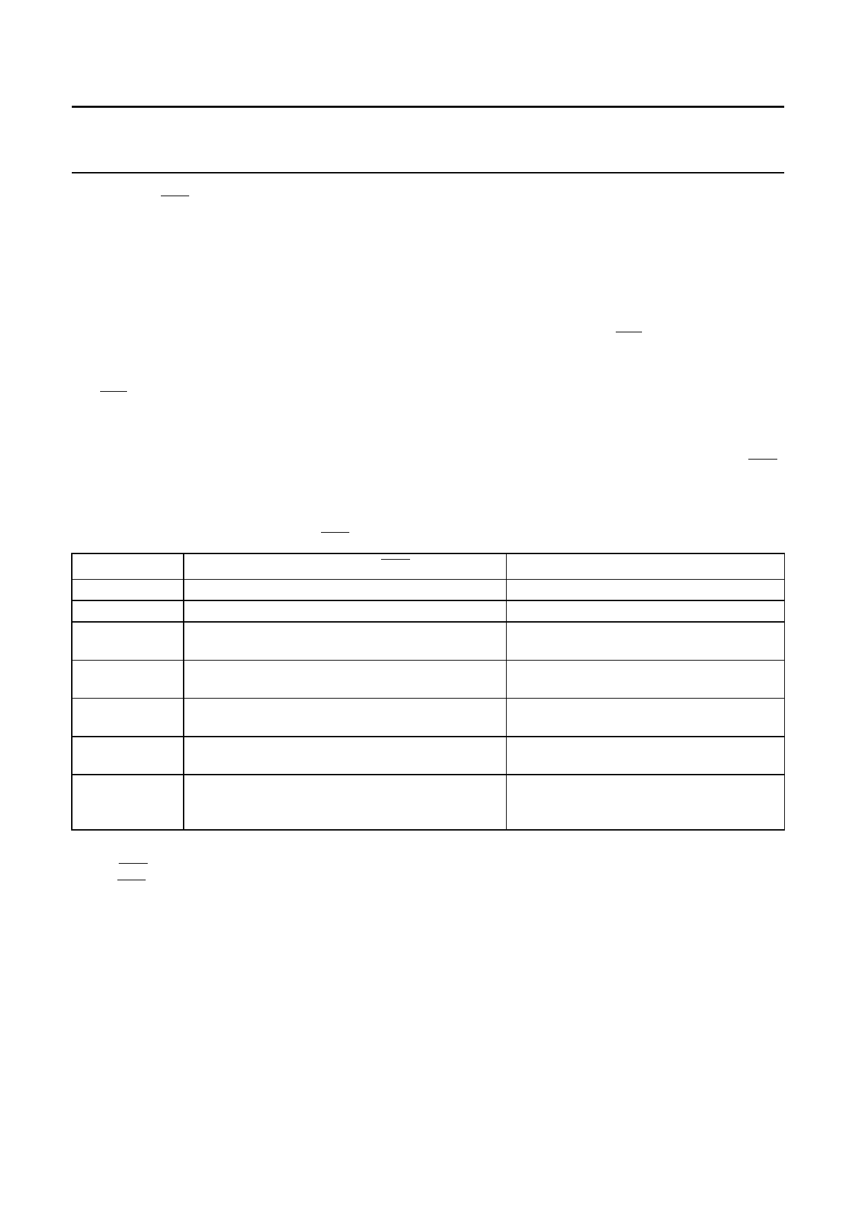
Table 2 Accessing internal flags via pin ERR.
Internal flag
UVNOM
UVBAT
pwon
wake-up
wake-up source
bus failure
local failure
Flag is available on pin ERR (note 1)
no
no
in pwon/listen-only mode (coming from standby
mode, go-to-sleep command mode, or sleep mode)
in standby mode, go-to-sleep command mode, and
sleep mode (provided that VI/O is present)
in normal mode (before the fourth dominant to
recessive edge on pin TXD; note 2)
in normal mode (after the fourth dominant to
recessive edge on pin TXD; note 2)
in pwon/listen-only mode (coming from normal
mode)
Flag is cleared
by setting the pwon or wake-up flag
when VBAT has recovered
on entering normal mode
on entering normal mode, or by setting the
pwon or UVNOM flag
on leaving normal mode, or by setting the
pwon flag
on re-entering normal mode
on entering normal mode or when RXD is
dominant while TXD is recessive (provided
that all local failures are resolved)
Notes
1. Pin ERR is an active-LOW output, so a LOW level indicates a set flag and a HIGH level indicates a cleared flag. Allow
pin ERR to stabilize for at least 8 µs after changing operating modes.
2. Allow for a TXD dominant time of at least 4 µs per dominant-recessive cycle.
2003 Feb 13
8
Share Link: 