TJA1050 데이터 시트보기 (PDF) - Philips Electronics
부품명
상세내역
제조사
TJA1050 Datasheet PDF : 16 Pages
| |||
Philips Semiconductors
High speed CAN transceiver
Preliminary specification
TJA1050
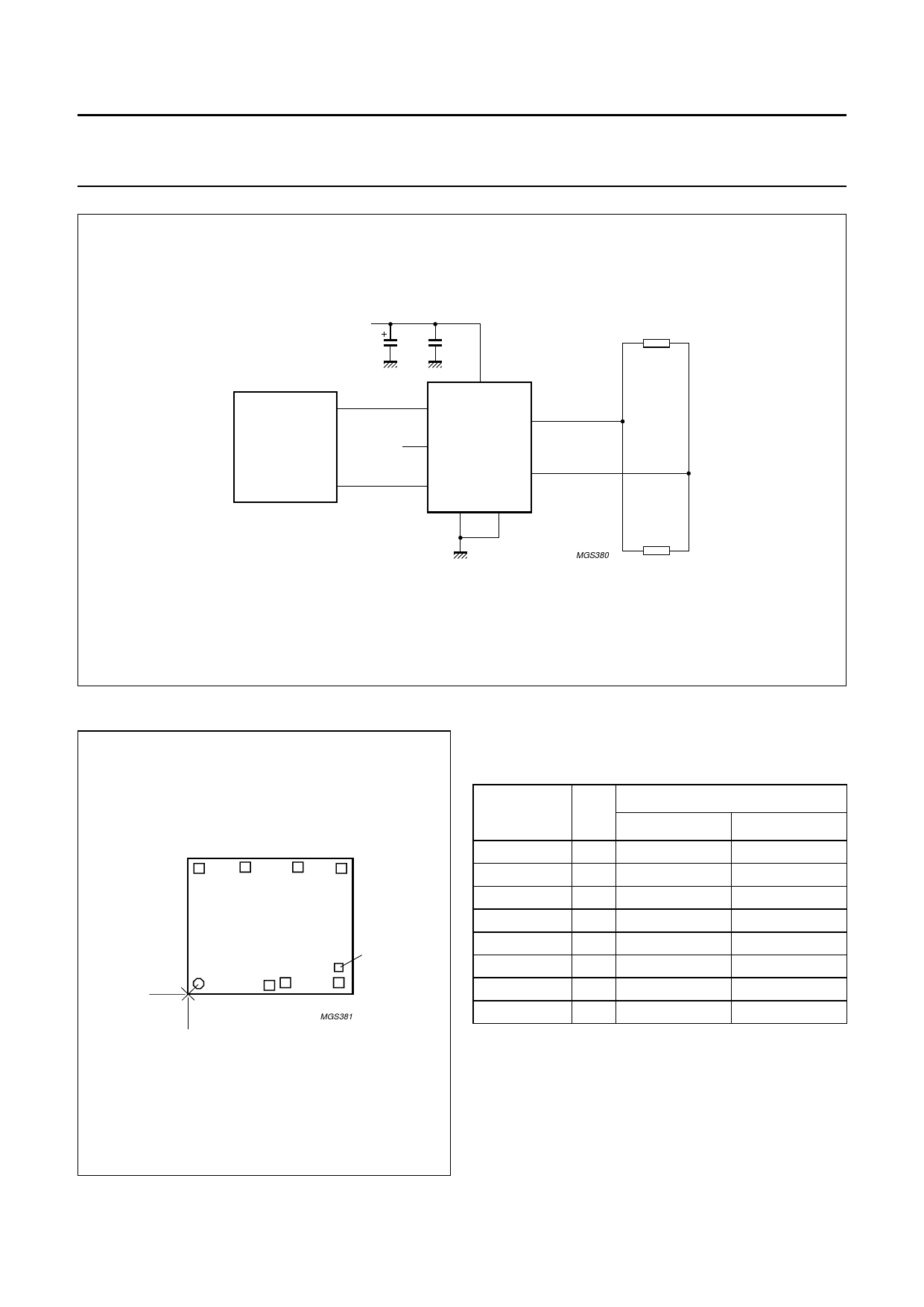
handbook, full pagewidth
+5 V
TX0
SJA1000
CAN
CONTROLLER
RX0
47
100
µF
nF
TXD
1
Vref 5
VCC
3
TJA1050
CANH
7
RXD
4
CANL
6
2
8
GND S
MGS380
120 Ω
CAN
BUS LINE
120 Ω
Fig.7 Application information.
BONDING PAD LOCATIONS FOR TJA1050U
handbook, halfpage
8
7
6
5
x
01
0
y
TJA1050U
test pad
23
4
MGS381
Table 2 Bonding pad locations
All x/y coordinates represent the position of the centre of
each pad (in µm) with respect to x/y = 0 of the die (see
Fig.8).
SYMBOL PAD
TXD
1
GND
2
VCC
3
RXD
4
Vref
5
CANL
6
CANH
7
S
8
COORDINATES
x
y
103
740.5
886.5
1371.5
1394
1006
542.5
103
103
85
111
111
1094
1111
1111
1097
Fig.8 Bonding pad locations.
1999 Sep 27
10
Share Link: 