TK15211 데이터 시트보기 (PDF) - Toko America Inc
부품명
상세내역
제조사
TK15211 Datasheet PDF : 12 Pages
| |||
TK15211
APPLICATION INFORMATION
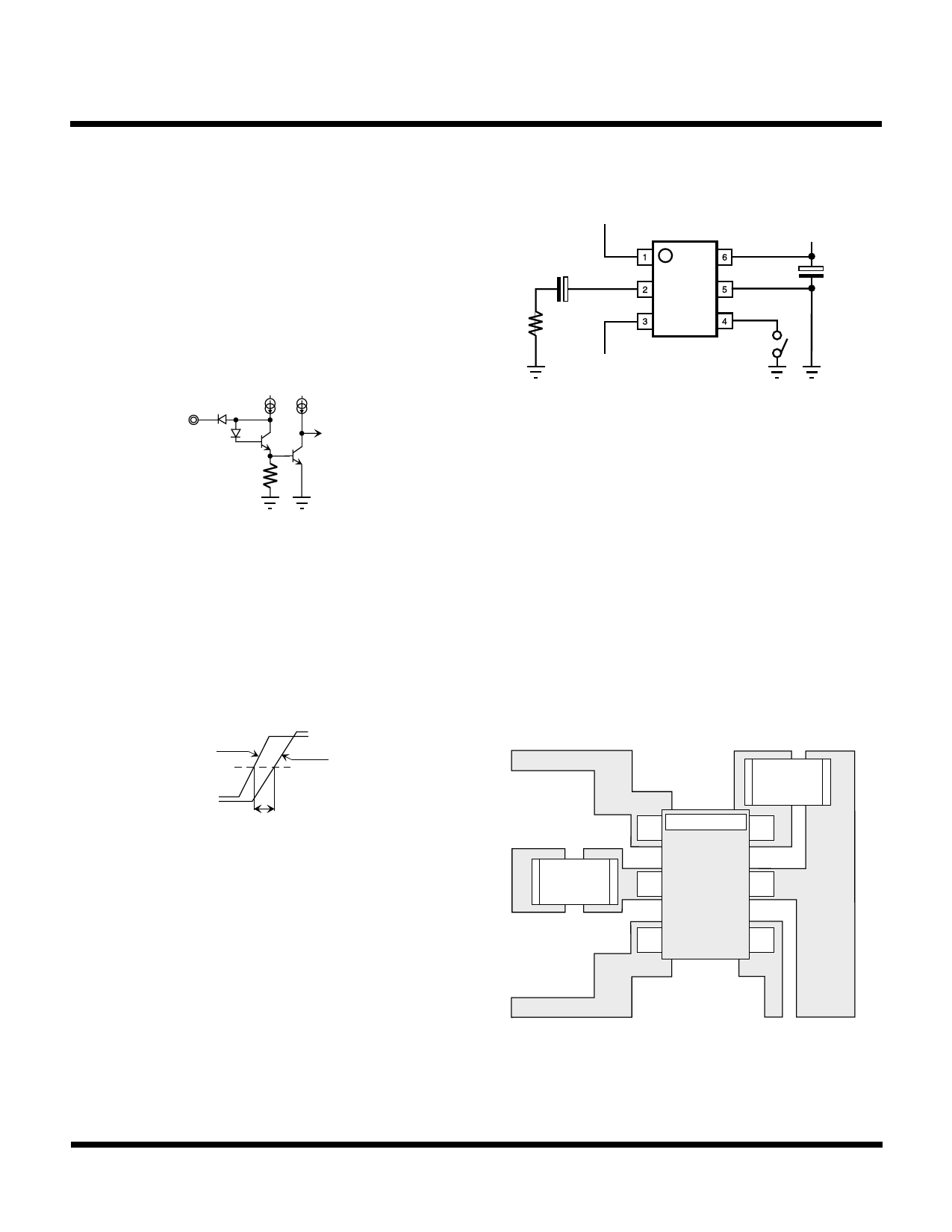
KEY INPUT CIRCUIT
Figure 10 illustrates the KEY input equivalent circuit. When
the control pin is open, the input is pulled up to a high level
(approximately 1.4 V). This applies the channel A input
signal to the output. A low level changes the output to the
channel B input signal. When the control terminal is pulled
low, a current up to 30 µA may flow out of the terminal. For
this reason, an external resistor value must be selected
which results in a voltage of less than 0.8 V to maintain a low
condition.
Key in
to Logic
inA
10 µF
out
+
RL
inB
Figure 12
VCC
+
33 µF
Key
Figure 10
SWITCHING TIME
This time is the signal change response time compared to
the control key input signal. Figure 11 illustrates the timing
chart. T = 2 µs typically.
Key in
50%
Bch (Ach)
SW out
t
Ach (Bch)
CROSS TALK
Figure 13 is an example of a layout pattern. Because the
TK15211M is direct coupled, the influence of the
application is minimal. However, in the capacitor coupled
application of the TK15211M, the following must be
considered. Because of the high impedance at the inputs,
the capacitors can act as antennas to each other. If the
parts are bigger, and the space between the capacitors is
too narrow, then cross talk will increase. Therefore, when
designing the printed circuit pattern, separate the input
capacitors as far as possible and use as small a part as
possible (e.g., surface mount types, etc.).
Figure 11
APPLICATION
Figure 12 illustrates an example of a typical application.
The standard application of the TK15211M is to use direct
coupling at the inputs and capacitor coupling at the output.
For characteristics of distortion and dynamic range versus
R , refer to the graphs in the Typical Performance
L
Characteristics. The TK15211M can also be used with
capacitor coupling on the inputs, but an external bias
supply is required. If capacitor coupling is desired, it is
recommended to use the TK15210M with built-in bias. The
DC input bias of the TK15210M is V /2
CC
June 1999 TOKO, Inc.
Figure 13
Page 9
Share Link: 