TK15403 데이터 시트보기 (PDF) - Toko America Inc
부품명
상세내역
제조사
TK15403 Datasheet PDF : 8 Pages
| |||
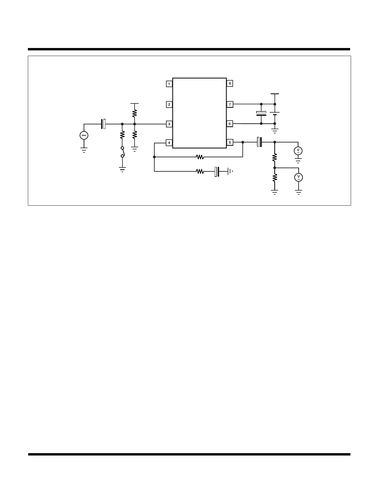
TEST CIRCUIT
Channel A is the same measurement
circuit as Channel B.
VCC
4.7 µF
TP1
+
10 kΩ
20 kΩ
10 kΩ
SW1
SW1 is closed only
when DG and DP
are measured.
2 kΩ
47 µF
+
2 kΩ
TK15403
VCC
+
33 µF
5V
47 µF
TP2
+
75 Ω
TP3
75 Ω
MEASUREMENT METHOD
1. Supply Current (ICC)
The Pin 7 current is measured with no input signal.
2. Voltage Gain (GVA)
The Voltage Gain equation is as follows:
GVA = 20 log10 V2/V1
Where V1 is the input voltage at TP1 and V2 is the measured voltage at TP2.
3. Frequency Response (fr1 and fr2)
The frequency response equation is as follows:
fr = 20 log10 V2/V1
Where V1 is the measured TP3 voltage when the TP1 input frequency is set to 1 MHz.
For fr1 V2 is the measured TP3 voltage when the TP1 input frequency is set to 5 MHz.
For fr2 V2 is the measured TP3 voltage when the TP1 input frequency is set to 10 MHz.
These measurements and calculations are taken for both channels.
4. Total Harmonic Distortion (THD)
The TP3 signal is measured when a 1 kHz 1 VP-P input signal is applied to TP1.
5. Maximum Output Voltage (V
)
OUT(MAX)
A 1 kHz input signal is applied to TP1 and slowly increased. The output voltage at TP2 is measured at the point the THD
reaches 10%.
6. Cross Talk (CT)
The Cross Talk equation is as follows:
CT = 20 log10 V1/V2
V1 is measured at output B when a 1 MHz input frequency and 1 VP-P input signal voltage is applied to Input A, V2 is
measured at Output B when a 1 MHz input frequency and 1 V input signal voltage is applied to Input B.
P-P
CT is also calculated at the opposite side when V1 is measured at Output A when input signal is applied to Input B and
V2 is measured at Output A when input signal is applied to Input A.
December 1999 TOKO, Inc.
Page 3
Share Link: 