TL431ACCT(2017) 데이터 시트보기 (PDF) - STMicroelectronics
부품명
상세내역
제조사
TL431ACCT Datasheet PDF : 21 Pages
| |||
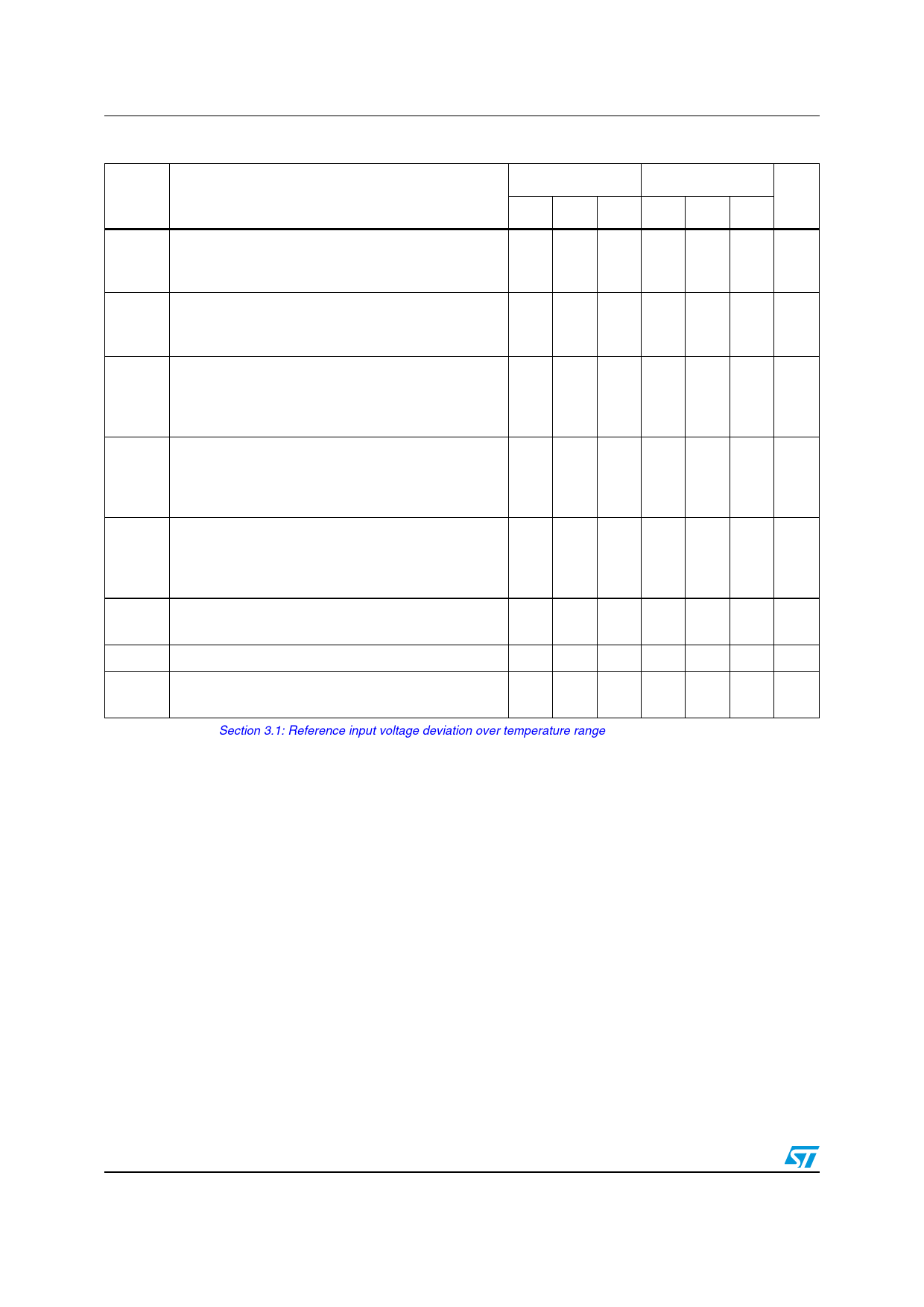
Electrical characteristics
TL431, TL432
Symbol
Table 4. TL431I/TL432I (Tamb = 25 °C unless otherwise specified)
Parameter
TL431I/TL432I TL431AI/TL432AI
Unit
Min. Typ. Max. Min. Typ. Max.
Vref
Vref
----VV---r-k-e--a-f
Reference input voltage
VKA = Vref, Ik = 10 mA, Tamb = 25 °C
Tmin Tamb Tmax
Reference input voltage deviation overtemperature
range (1)
VKA = Vref, Ik =10 mA, Tmin Tamb Tmax
Ratio of change in reference input voltage to change
in cathode to anode voltage
Ik = 10 mA, VKA = 10 V to Vref
VKA = 36 V to 10 V
2.44 2.495 2.55 2.47 2.495 2.52 V
2.41 - 2.58 2.44 - 2.55
-
7 30 -
7 30 mV
-2.7 -1.4
-2 -1
-
-
-2.7 -1.4
-2 -1
- mV/V
-
Reference input current
Iref
Ik = 10 mA, R1 = 10 k, R2 =
Tamb = 25 °C
Tmin Tamb Tmax
-
-
1.8 4
- 6.5
-
-
1.8
-
4
6.5
µA
Iref
Imin
Ioff
ZKA
Reference input current deviation overtemperature
range
Ik = 10 mA, R1 = 10 k, R2 =
Tmin Tamb Tmax
Minimum cathode current for regulation
VKA = Vref
Off-state cathode current
Dynamic impedance(2)
VKA = Vref, Ik = 1 to 100 mA, f 1 kHZ
- 0.8 2.5 - 0.8 1.2 µA
- 0.5 1
- 0.5 0.7 mA
- 2.6 1000 - 2.6 1000 nA
- 0.22 0.5 - 0.22 0.5
1. See definition of Section : Reference input voltage deviation overtemperature range below.
2. The dynamic impedance is defined as ZKA= -----V---I-K-k---A--
6/21
DocID4467 Rev 12
Share Link: 