TSDF1205 데이터 시트보기 (PDF) - Vishay Semiconductors
부품명
상세내역
제조사
TSDF1205 Datasheet PDF : 7 Pages
| |||
TSDF1205 / 1205R / 1205W / 1205RW
Vishay Semiconductors
Electrical AC Characteristics
Tamb = 25 °C, unless otherwise specified
Parameter
Test condition
Symbol
Min
Typ.
Max
Unit
Transition frequency
VCE = 2 V, IC = 5 mA, f = 1 GHz
fT
12
GHz
Collector-base capacitance
VCB = 1 V, f = 1 MHz
Ccb
0.2
pF
Collector-emitter capacitance VCE = 1 V, f = 1 MHz
Cce
0.35
pF
Emitter-base capacitance
VEB = 0.5 V, f = 1 MHz
Ceb
0.15
pF
Noise figure
VCE = 2 V, IC = 2 mA, ZS = ZSopt,
F
ZL = 50 Ω, f = 2 GHz
1.3
dB
Power gain
VCE = 2 V, IC = 2 mA, f = 2 GHz
Gpe
13
dB
(at Fopt)
VCE = 2 V, IC = 5 mA, ZS = ZSopt,
Gpe
11.5
dB
ZL = 50 Ω f = 2 GHz
Transducer gain
VCE = 2 V, IC = 5 mA, Z0 = 50 Ω,
|S21e|2
12.5
dB
f = 2 GHz
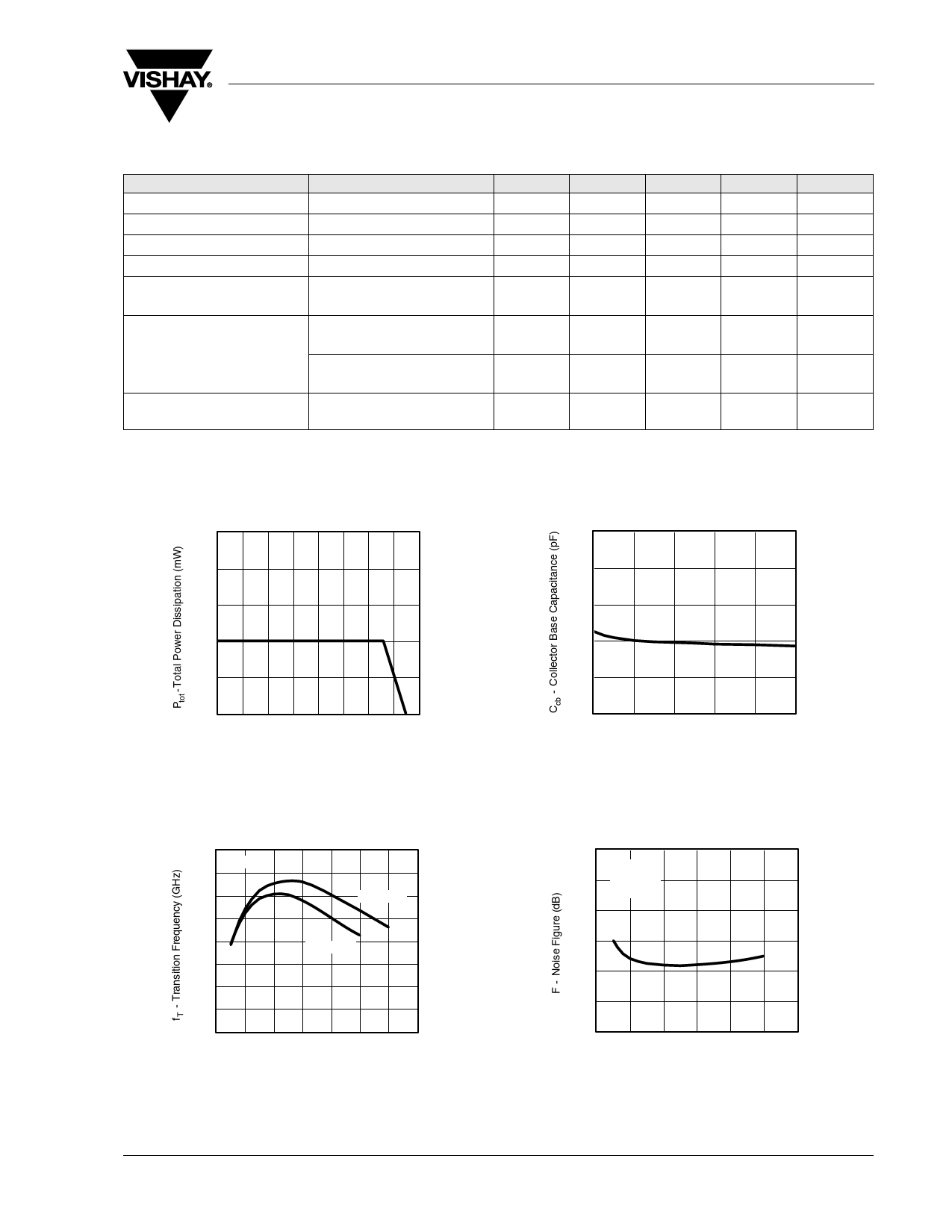
Typical Characteristics
Tamb = 25 °C, unless otherwise specified
100
80
60
40
20
0
0
14284
20 40 60 80 100 120 140 160
Tamb - Ambient Temperature (°C)
Figure 1. Total Power Dissipation vs. Ambient Temperature
0.5
0.4
0.3
0.2
0.1
0.0
0
1
2
3
4
5
14286
VCB - Collector Base Voltage (V)
Figure 3. Collector Base Capacitance vs. Collector Base Voltage
16
f =1 GHz
14
12
VCE = 3 V
10
8
VCE = 2 V
6
4
2
0
0
14285
2 4 6 8 10 12 14
IC - Collector Current (mA)
Figure 2. Transition Frequency vs. Collector Current
3.0
VCE = 2 V
2.5 f = 2 GHz
ZS = 50 Ω
2.0
1.5
1.0
0.5
0.0
0
1
2
3
4
5
6
14287
IC - Collector Current (mA)
Figure 4. Noise Figure vs. Collector Current
Document Number 85065
Rev. 1.7, 08-Sep-08
www.vishay.com
3
Share Link: 