TSL1014 데이터 시트보기 (PDF) - STMicroelectronics
부품명
상세내역
제조사
TSL1014 Datasheet PDF : 16 Pages
| |||
TSL1014
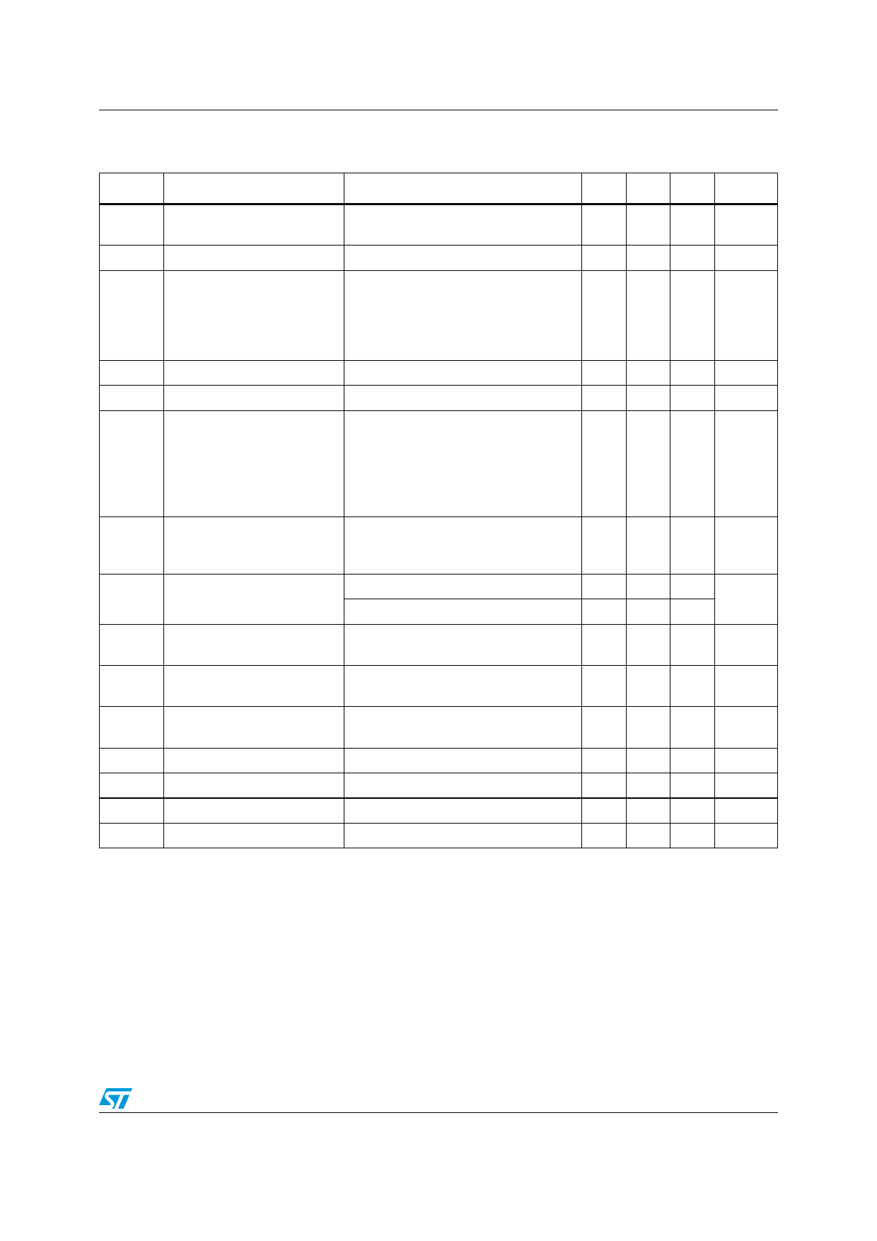
Electrical characteristics
Table 4.
Symbol
Electrical characteristics for TSL1014IYF/TSL1014IYFT (automotive grade)
Tamb = 25°C, VDD = +5V, VSS = -5V, RL = 10kΩ, CL = 10pF (unless otherwise specified)
Parameter
Test conditions
Min. Typ. Max. Unit
VIO
ΔVIO
IIB
RIN
CIN
VOL
VOH
IOUT
PSRR
ICC
SR
ts
BW
Gm
Cs
Input offset voltage
Input offset voltage drift
Input bias current
Input impedance
Input capacitance
Output voltage low
Output voltage high
Output current
Power supply rejection ratio
Supply current
Slew rate
(rising & falling edge)
Settling time
Bandwidth at -3dB
Phase margin
Channel separation
VICM = 0V
TMin < Tamb < TMax
TMin < Tamb < TMax
VICM = 0V, buffers A & B
TMin < Tamb < TMax
VICM = 0V, buffers C to N & COM
TMin < Tamb < TMax
IOUT = -5mA
Buffers C to L
TMin < Tamb < TMax
Buffers M, N & COM
TMin < Tamb < TMax
IOUT = 5mA for positive single-supply
buffers (A & B)
TMin < Tamb < TMax
(A to N buffers)
Com buffer
VCC= 6.5 to 15.5V
TMin < Tamb < TMax
No load
TMin < Tamb < TMax
-4V < VOUT < +4V
20% to 80%
Settling to 0.1%, VOUT=2V step
RL=10kΩ, CL=10pF
RL=10kΩ, CL=10pF
f=1MHz
12
5
140
280
70
140
1
1.35
mV
μV/°C
nA
GΩ
pF
-4.85 -4.80
-4.76
V
-4.92 -4.85
-4.83
4.82 4.87
V
4.80
±30
mA
±100
100
80
dB
6 8.4
9
mA
1
V/μs
5
μs
2
MHz
60
degrees
75
dB
Note:
Limits are 100% production tested at 25°C. Behavior at the temperature range limits is
guaranteed through correlation and by design.
5/16
Share Link: 