UEI25-120-D48P-C(2010) 데이터 시트보기 (PDF) - Murata Manufacturing
부품명
상세내역
제조사
UEI25-120-D48P-C Datasheet PDF : 11 Pages
| |||
UEI25-120 Series
Single Output Isolated 25-Watt DC/DC Converters
PERFORMANCE SPECIFICATIONS AND ORDERING GUIDE ➀
Output
Input
Root Models ➀
R/N (mVp-p) Regulation (Max.)
IIN, IIN,
IOUT Total
VIN
min. full
VOUT (A, Power
Nom. Range load load
(V) max) (W) Typ. ➁ Max. Line Load (V) (V) (mA) (A)
Efficiency
Min. Typ.
Package, C75
Case (inches) Case (mm)
Pinout
UEI25-120-D48 ➃
12 2.1 25.2 95 120 ±0.1% ±0.1% 48 36-75 20 0.6 86.0% 87.5% 0.96x1.1x0.32 24.38x27.94x8.13 P85
Notes:
➀ Please refer to the part number structure for additional options and complete ordering
part numbers.
➁ Ripple and Noise is shown at 20 MHz bandwidth.
➂ All specifications are at nominal line voltage and full load, +25 deg.C. unless otherwise
noted. See detailed specifications for full conditions.
(Note ➂ Continued) Output capacitors are 1 μF ceramic in parallel with 10 μF electrolytic.
The input cap is 47 μF ceramic, low ESR.
I/O caps are necessary for our test equipment and may not be needed for your ap-
plication.
➃ UL certification is pending.
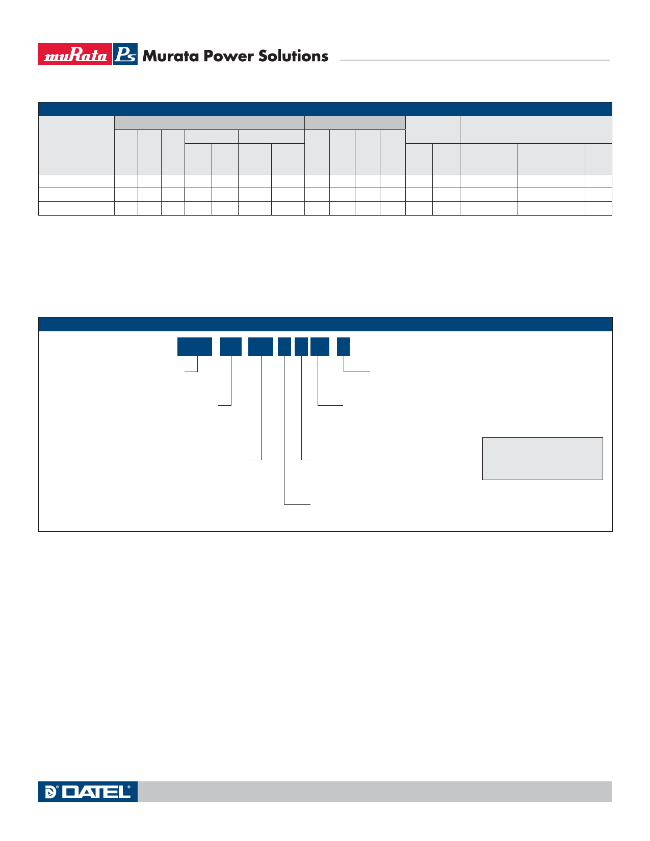
PART NUMBER STRUCTURE
UEI25 - 120 - D48 P Lx - C
Unipolar Ouput Isolated
25-Watt Series
RoHS-6 Hazardous Substance Compliance
(Does not claim EU RoHS exemption 7b, lead in solder)
Nominal Output Voltage
in Tenths of a Volt
Input Voltage Range
D48 = 36-75 Vdc
Pin Length Option
Blank = Std. pin length 0.25˝ (6.3mm)
L1 = 0.110˝ (2.79mm)*
L2 = 0.145˝ (3.68mm)*
On/Off Control Polarity:
P = Positive
N = Negative
Note:
Some model number combinations
may not be available.
Contact Murata Power Solutions.
*Alternate pin lengths
require quantity order.
www.murata-ps.com
email: sales@murata-ps.com
17 Aug 2010 MDC_UEI25-120.A02 Page 2 of 11
Share Link: 