UPD16641N 데이터 시트보기 (PDF) - NEC => Renesas Technology
부품명
상세내역
제조사
UPD16641N Datasheet PDF : 20 Pages
| |||
µPD16641
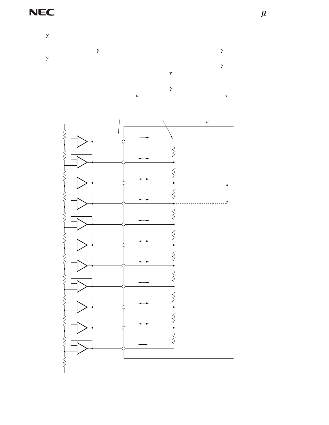
γ-Corrected Power Circuit
The reference power supply of the D/A converter consists of a ladder circuit with a total of 64 resistors, and
resistance Σri between γ-corrected power pins differs depending on each pair of γ-corrected power pins. One pair of
γ-corrected power pins consists of seven or eight series resistors, and resistance Σri in the figure below is indicated
as the sum of the seven of eight resistors. The resistance ratio between the γ-corrected power pins (Σri ratio) is
designed to be a value relatively close to the ratio of the γ-corrected voltages V1 through V9 (gray scale voltages in 8
steps) used in an actual LCD panel. Under ideal conditions where there is no difference between the two, therefore,
there is no voltage difference between the voltage of the γ-corrected power supplies and the gray scale voltages in 8
steps of the resistor ladder circuits of the µPD16641, and no current flows into the γ-corrected power pins V1 through
V9. As a result, a voltage follower circuit is not necessary.
γ-corrected power pin
γ-corrected resistor
µ PD16641
–
V0
i0
+
R0 = 1.81 kΩ
–
V1
i1
+
7
R1 = Σri = 3.57 kΩ
i=1
–
V2
i2
+
8
R2 = Σri = 3.12 kΩ
i=1
Sum of eight
γ-corrected resistors
–
V3
i3
+
8
R3 = Σri = 3.08 kΩ
i=1
–
V4
i4
+
8
R4 = Σri = 2.90 kΩ
i=1
–
V5
i5
+
8
R5 = Σri = 2.32 kΩ
i=1
–
V6
i6
+
8
R6 = Σri = 3.35 kΩ
i=1
–
V7
i7
+
8
R7 = Σri = 3.23 kΩ
i=1
–
V8
i8
+
7
R8 = Σri = 4.75 kΩ
i=1
–
V9
i9
+
R9 = 13.5 kΩ
–
V10
i10
+
7
Share Link: 