CXA1854AR 데이터 시트보기 (PDF) - Sony Semiconductor
부품명
상세내역
제조사
CXA1854AR Datasheet PDF : 45 Pages
| |||
CXA1854AR
Setting Conditions for Measuring Electrical Characteristics
When measuring the DC characteristics, the TG block must be horizontally synchronized by performing Setting 2.
Setting 2 must also be performed when measuring the AC characteristics. When measuring items with bands
greater than 2MHz such as the Y frequency response or sharpness characteristics, settings 1 and 3 must also
be performed and measurements made with the sample-and-hold circuit set to through status.
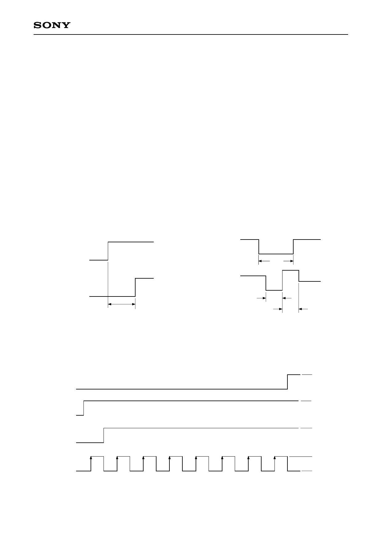
Setting 1. System reset
After turning on the power, set SW52 to ON and start up V52 from GND in order to activate the
timing controller system reset. (See Fig. 1-1.)
Setting 2. Horizontal AFC adjustment
Input SIG6 (VL = 0mV) to (A) and adjust VR12 so that WL and WH of the TP12 output waveform are
the same. (See Fig. 1-2.)
Setting 3. S/H off
Input the signals shown in Fig. 1-3 to Pins 16, 17, 18 and 19 in order to set the sample-and-hold
circuit to through status.
VDD (VCC1)
V52 (RESET)
TR > 10µs
TR
Fig. 1-1. System reset
SIG6
TP12
WS
WL
WL = WH
WH
Fig. 1-2. Horizontal AFC adjustment
Pin 19
Pin 18
Pin 17
Pin 16
Fig. 1-3. S/H off input pattern
– 10 –
VDD
GND
VDD
GND
VDD
GND
VDD
GND
Share Link: 