VRE107(2009_03) 데이터 시트보기 (PDF) - Cirrus Logic
부품명
상세내역
제조사
VRE107 Datasheet PDF : 5 Pages
| |||
Product Innova tionFrom
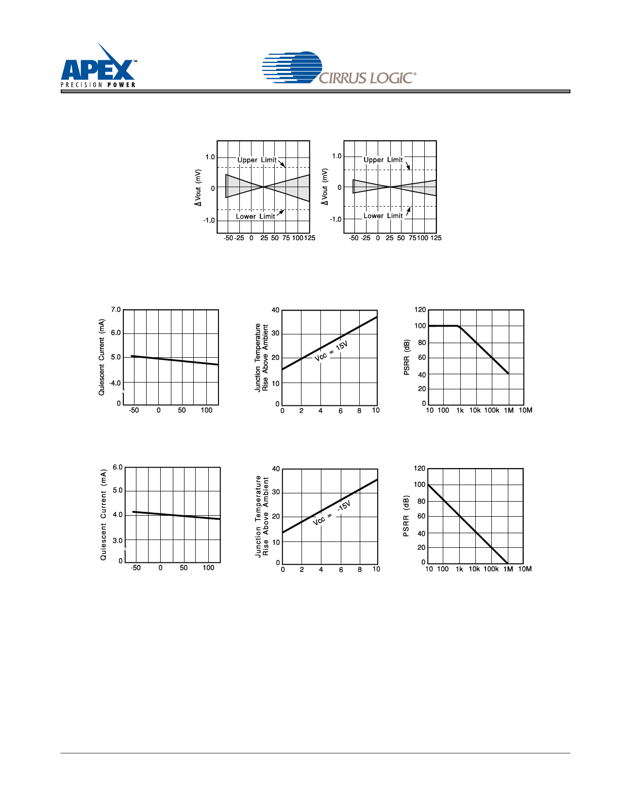
TYPICAL PERFORMANCE GRAPHS
VOUT vs. TEMPERATURE
VOUT vs. TEMPERATURE
VRE107
Temperature oC
VRE107M
Temperature oC
VRE107MA
QUIESCENT CURRENT VS. TEMP
POSITIVE OUTPUT
JUNCTION TEMP. RISE VS. OUTPUT CURRENT
PSRR VS. FREQUENCY
Temperature oC
QUIESCENT CURRENT VS. TEMP
Output Current (mA)
NEGATIVE OUTPUT
JUNCTION TEMP. RISE VS. OUTPUT CURRENT
Frequency (Hz)
PSRR VS. FREQUENCY
Temperature oC
Output Current (mA)
Frequency (Hz)
2. THEORY OF OPERATION
The following discussion refers to the block diagram in Figure 1. A FET current source is used to bias a 6.3 V zener
diode. The zener voltage is divided by the resistor network R1 and R2. This voltage is then applied to the noninvert-
ing input of the operational amplifier which amplifies the voltage to produce a 5 V output. The gain is determined by
the resistor networks R3 and R4: G=1 + R4/R3. The 6.3 V zener diode is used because it is the most stable diode
over time and temperature.
The current source provides a closely regulated zener current, which determines the slope of the reference’s volt-
age vs. temperature function. By trimming the zener current, a lower drift over temperature can be achieved. But
since the voltage vs. temperature function is nonlinear, this method leaves a residual error over wide temperature
ranges.
VRE107DS
Share Link: 